Minimized wave-zone buoyancy platform

a buoyancy platform and wave-zone technology, applied in the direction of special-purpose vessels, vessel construction, transportation and packaging, etc., can solve the problems of high structure forces, excessive ancillary structures, and higher associated costs for materials, construction, installation, etc., to minimize wave-zone buoyancy, high structure forces, and higher associated costs

Inactive Publication Date: 2006-08-31
CHOW ANDREW W
View PDF9 Cites 8 Cited by
  • Summary
  • Abstract
  • Description
  • Claims
  • Application Information

AI Technical Summary

Benefits of technology

[0005] The drawbacks of the current technology stem from high platform wave-zone buoyancy that leads to high forces on the structure from waves and swells. The negative consequences of not minimizing wave-zone buoyancy include: excessive ancillary structures, higher associated costs for materials, construction, and installation, extended schedule for construction and installation thus delaying start of oil and gas production, inferior performance such as less stable platforms and reduced portability, and shorter fatigue lives for components attached to the platforms.

Problems solved by technology

The drawbacks of the current technology stem from high platform wave-zone buoyancy that leads to high forces on the structure from waves and swells.
The negative consequences of not minimizing wave-zone buoyancy include: excessive ancillary structures, higher associated costs for materials, construction, and installation, extended schedule for construction and installation thus delaying start of oil and gas production, inferior performance such as less stable platforms and reduced portability, and shorter fatigue lives for components attached to the platforms.

Method used


Image

  • Minimized wave-zone buoyancy platform
  • Minimized wave-zone buoyancy platform

Examples


Embodiment Construction

Physics of Dynamics of Motion

[0009] Dynamics of motion is governed by a commonly known differential equation

MA+CV+KX=F(t)

which basically represents a balance of forces. In essence the sum of mass times acceleration, friction forces related to velocity, and distance-proportional reactive forces must be equal to the forcing function. Engineers can model complicated structures by developing mass and stiffness matrices and solve for numerical solutions. In the case of earthquake analysis, such as for an above-ground petroleum pipeline like the one in Alaska, the forcing function could be a seismic event's ground-motion that drives the structure's dynamic response over time.

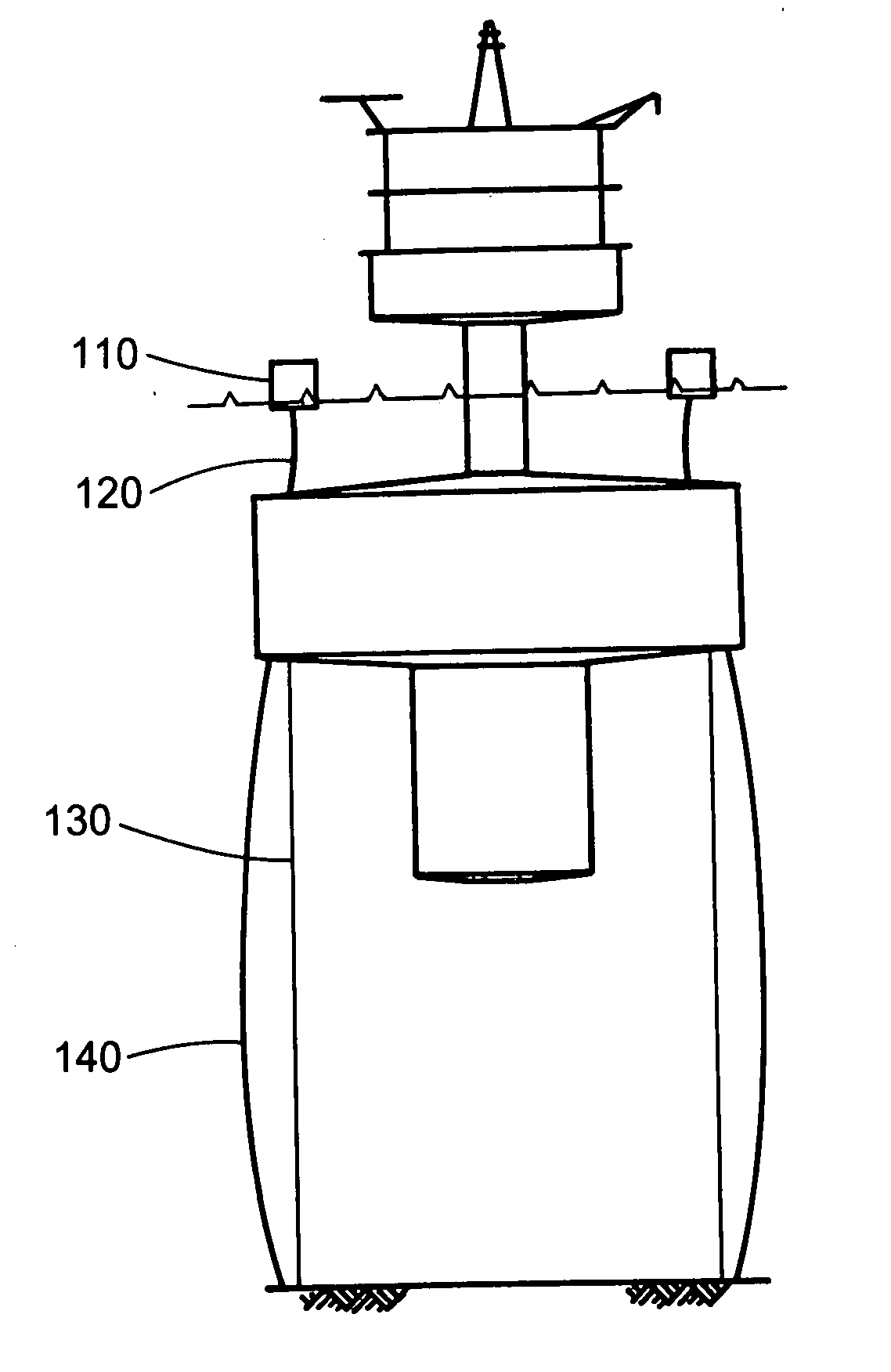
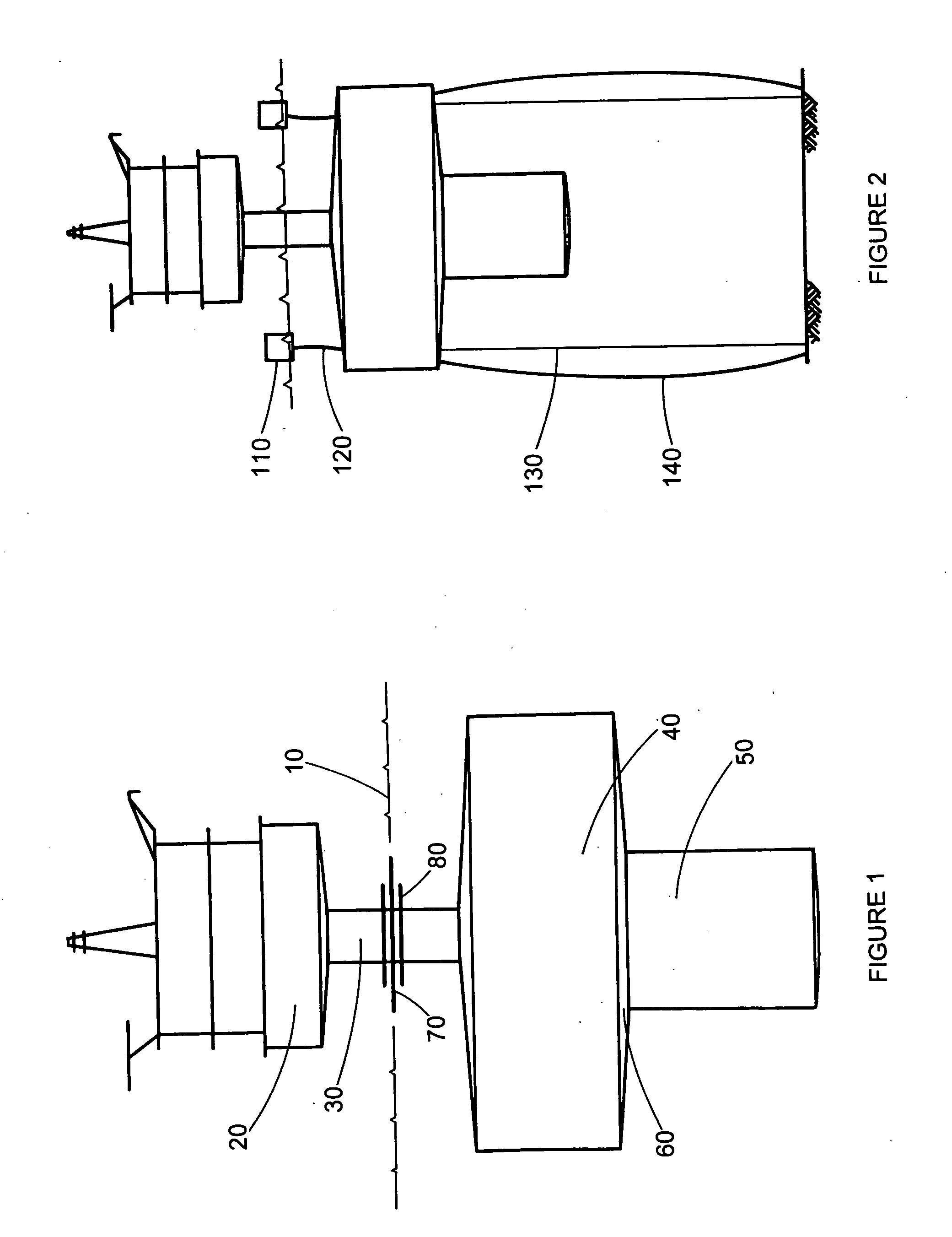
[0010] As a floating production platform behaves like a rigid body bobbing in water, the dynamic equation of motion degenerates to the most basic one degree of freedom spring mass type system where the natural frequency of oscillation, ω, for the solution to the stated differential equation is defined by the foll...


PUM


Abstract

Minimized Wave-zone Buoyancy is a new approach to oil and gas platform design with superior construction and performance characteristics compared to state-of-art off-shore drilling and production platforms. Minimized Wave-zone Buoyancy platforms capitalize on low cross sectional area of the portion of the platform exposed to waves. The low cross sectional area reduces buoyancy forces that result from vertical platform movement, enabling the platform to oscillate at a low natural frequency. The low cross sectional area also minimizes the cyclical vertical forces induced by waves. Compare to current designs, application of the Minimized Wave-zone Buoyancy concept will result in a lower natural frequency of oscillation, lower overall weight of platform, or both. Minimized Wave-zone Buoyancy offers an attractive alternative with improved platform stability, fatigue considerations, lower construction and installation costs, and shorter implementation schedule.

Description

CROSS-REFERENCE TO RELATED APPLICATION [0001] Application Ser. No. 09 / 751,264 of same title above was filed on Jan. 2, 2001, with Art Unit 3673 and Examiner Mr. Frederick L. Lagman. The current application files again the same invention of the prior application, continued and abandoned due to office action response lost in mail and lacking proof of timely submission. While the U.S. Patent and Trademark Office would consider this application officially as a new filing with a new date, the inventor in essence continues to, process the same invention as before.STATEMENT REGARDING FEDERALLY SPONSORED RESEARCH OR DEVELOPMENT [0002] not applicable INCORPORATED BY REFERENCE OF MATERIAL SUBMITTED ON A COMPACT DISC [0003] not applicable BACKGROUND OF THE INVENTION Discussion of Current Deep-Water Floating Design [0004] As oil and gas operations extend farther and farther out into deeper ocean areas, new technology has facilitated the petroleum industry's ability to manage production in more ...

Claims


Application Information

Patent Timeline
Patent Type & Authority Applications(United States)
IPC IPC(8): B63B35/44B63B1/10
CPCB63B1/107B63B35/4406B63B1/048B63B39/005B63B2001/044
Inventor CHOW, ANDREW W.
Owner CHOW ANDREW W
Why Eureka
Try Eureka