Optical pickup

Inactive Publication Date: 2008-08-07
HITACHI MEDIA ELECTORONICS CO LTD
View PDF10 Cites 4 Cited by
  • Summary
  • Abstract
  • Description
  • Claims
  • Application Information

AI Technical Summary

Benefits of technology

[0010]In view of the foregoing, an object of the invention is to provide an optical pickup in which the optical axis of the optical element is not displaced even if the ambient temperature is changed.
[0012]A thermal expansion amount of the optical unit is absorbed by a compression amount of the first adhesive and a compression amount of the second adhesive such that the optical axis of the lens member is not displaced when the optical unit is thermal expanded.

Problems solved by technology

However, curing, contraction, and swelling are generated in the adhesive as time advances or by a change in ambient temperature.
In the optical element in which the drive motor, the guide shaft, the holding member for holding the lens are provided around the lens, like the aberration correction element, it is difficult that the lens is arranged in the center position of the optical component.
In such structures, the change in ambient temperature easily causes the displacements of the position and inclination of the lens.
When the optical axis is displaced by the displacements of the position or inclination of the lens, the aberration is generated in a spot of the laser beam focused on the recording layer of the optical disk, which results in the problem that high-density recording is hardly performed.

Method used


Image

  • Optical pickup
  • Optical pickup
  • Optical pickup

Examples


first embodiment

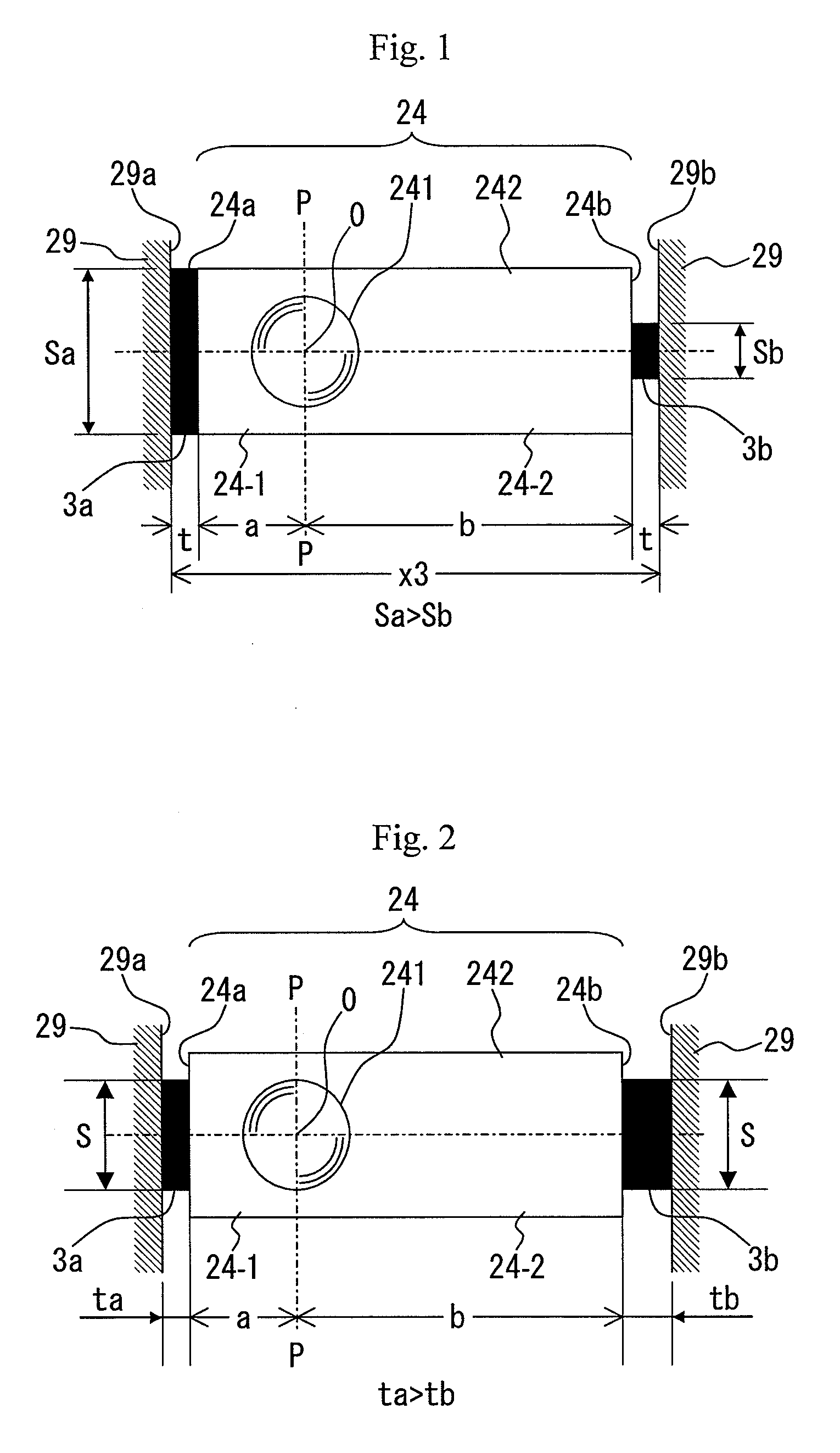
[0024]In the first embodiment, an optical axis O of the lens member 241 is offset from the center of the optical unit 24. As shown in FIG. 1, the optical unit 24 is imaginarily divided into two portions by a plane p-p passing through the optical axis O of the lens member 241. It is assumed that a first portion 24-1 is the portion ranging from the plane p-p passing through the optical axis O of the lens member 241 to the end face 24a of the optical unit 24 while a second portion 24-2 is the portion ranging from the plane p-p passing through the optical axis O of the lens member 241 to the end face 24b of the optical unit 24. It is assumed that a is a dimension in an axis line direction of the first portion 24-1 and b is a dimension in the axis line direction of the second portion 24-2. The dimension a of the first portion 24-1 is smaller than the dimension b of the second portion 24-2, i.e., a<b.

[0025]In the first embodiment, a bonding area Sa of the first adhesive 3a is larger than ...

fourth embodiment

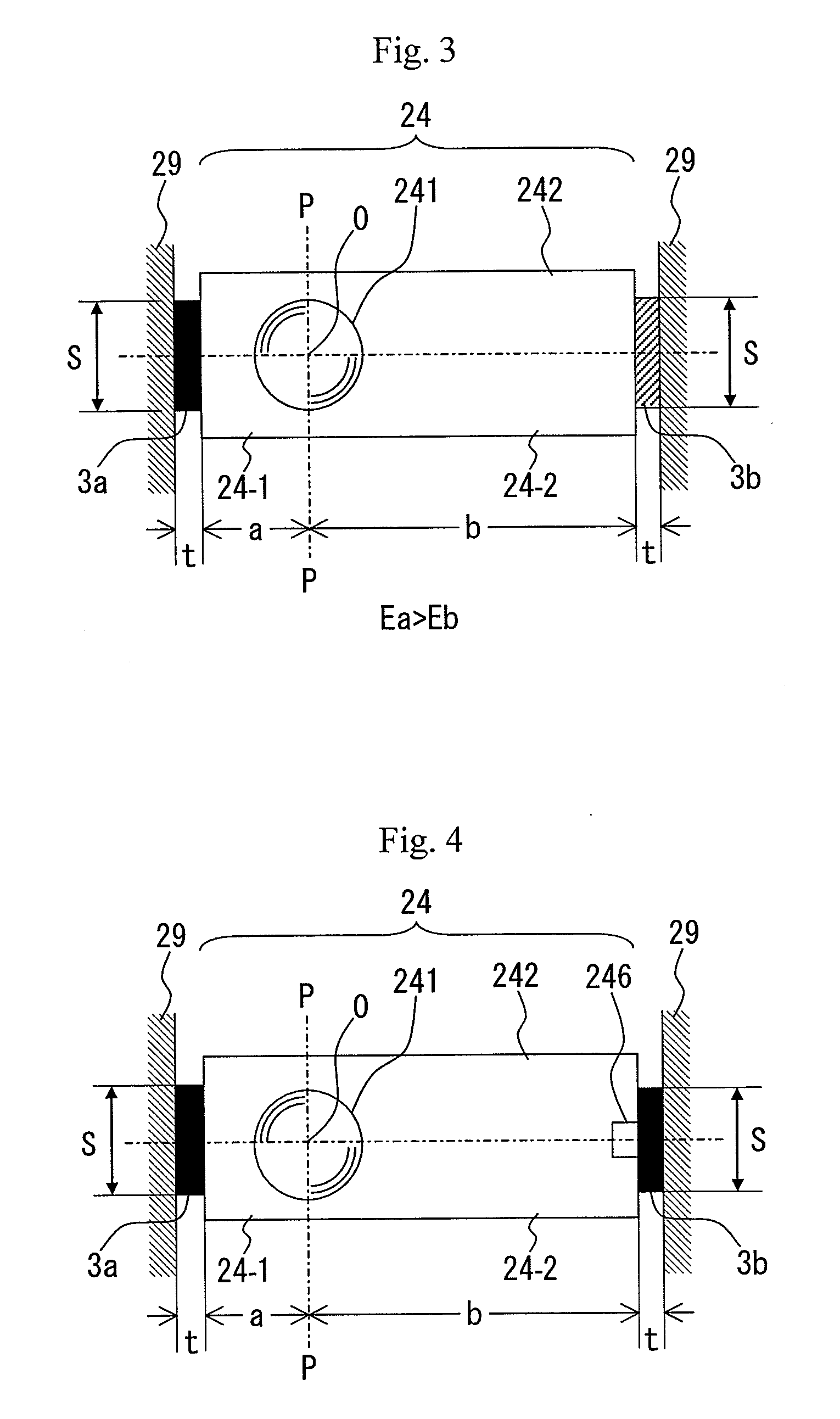
[0056]Formula 8 holds because the compression amount Δta of the first adhesive 3a is smaller than the compression amount Δtb of the second adhesive 3b. In the fourth embodiment, it is necessary that the amount of adhesive filled with into the recess 246 be adjusted such that Formula 5 holds.

[0057]In the fourth embodiment, the dimension a of the first portion 24-1 is smaller than the dimension b of the second portion 24-2. However, the dimension a of the first portion 24-1 may be larger than the dimension b of the second portion 24-2. In this case, the small recess is provided in the end face 24a on the opposite side of the optical unit 24.

[0058]An optical pickup according to a fifth embodiment of the invention will be described with reference to FIG. 5. In the optical pickup of the fifth embodiment, a small recess 291 is provided in the inner surface 29b of the recess of the optical pickup case 29, and the recess 291 is covered with the adhesive 3b. Other configurations of the optic...

fifth embodiment

[0061]Formula 8 holds because the compression amount Δta of the first adhesive 3a is smaller than the compression amount Δtb of the second adhesive 3b. In the fifth embodiment, it is necessary that the amount of adhesive filled with into the recess 291 be adjusted such that Formula 5 holds.

[0062]In the fifth embodiment, the dimension a of the first portion 24-1 is smaller than the dimension b of the second portion 24-2. However, the dimension a of the first portion 24-1 may be larger than the dimension b of the second portion 24-2. In this case, the small recess is provided in the inner surface 29a on the side opposite from the recess of the optical pickup case 29.

[0063]An optical pickup according to a sixth embodiment of the invention will be described with reference to FIGS. 6a and 6b. The optical unit 24 and the optical pickup case 29 will be described below. The optical unit 24 is a main part of the optical pickup, and the optical pickup case 29 holds the optical unit 24. FIG. 6...


PUM


Abstract

An aspect of the invention provides an optical pickup in which an optical axis is not displaced even if ambient temperature is changed. The optical pickup of the invention has an optical unit and an optical pickup case. The optical unit has a lens member having an optical axis, and the optical axis of the lens member is offset to one side from the center of the optical unit. The optical pickup case holds the optical unit from both sides. A thermal expansion amount of the optical unit is absorbed by compression amounts of a first adhesive and a second adhesive such that the optical axis of the lens member is not displaced when the optical unit is thermal expanded.

Description

1. FIELD OF THE INVENTION[0001]The present invention relates to an optical pickup used in an optical disk drive in which information is written in and read from a recording surface of an optical disk.2. BACKGROUND OF THE INVENTION[0002]In the optical pickup, a laser beam is focused on a recording surface of the optical disk, and the laser beam is detected from the recording surface of the optical disk. The optical pickup is formed by a combination of optical elements such as a laser, a mirror, a lens and a photodetector. For an optical axis of the optical element, position accuracy and inclination accuracy which affect aberration of the laser beam are important in the reading and writing operations.[0003]In the optical pickup, an optical pickup case having high stiffness is used to maintain the position accuracy and inclination accuracy of the optical element. The optical element is directly fixed to the optical pickup case with an adhesive, or the optical element is fixed to the op...

Claims


Application Information

Patent Timeline
IPC IPC(8): G11B7/00
CPCG11B7/1378G11B7/13922G11B2007/13727G11B7/13927G11B2007/0006G11B7/13925
Inventor KINOSHITA, YASUSHIKATOU, SEIICHIKIMURA, KATSUHIKOONO, SEIJIKURODA, NAOMITSUSAITO, HIDENAO
Owner HITACHI MEDIA ELECTORONICS CO LTD
Why Eureka
Try Eureka