
Ventilated and resilient shoe apparatus and system

a shoe apparatus and resilient technology, applied in the field of wearable objects, can solve the problems of odor-causing bacteria in the shoe interior, the inability of the shoe to allow the free flow of air through the inside of the shoe, and the athlete's foot and making such shoes smell, so as to reduce, if not eliminate, the pressure on the wearer's spine, knees, and other joints

Inactive Publication Date: 2008-08-14
ELNEKAVEH ALEXANDER
View PDF65 Cites 27 Cited by
  • Summary
  • Abstract
  • Description
  • Claims
  • Application Information

AI Technical Summary

Benefits of technology

[0010]The invention includes a novel shoe in one embodiment that is ventilated with external air. The apparatus and system circulate air around the wearer's foot without impacting the stability or comfort of an individual's walk. Circulating air throughout the shoe while an individual is walking provides an additional benefit that conventional shoes do not provide: reducing athlete's foot and foot odor. Conventional shoes do not allow the free flow of air throughout the inside of the shoe. Moisture and bacteria build up inside most conventional shoes, causing athlete's foot and making such shoes smell. The present invention provides that with every step, the individual is circulating fresh air throughout the shoe and around his foot. The result is a shoe interior that will not be a breeding ground for odor-causing bacteria. The wearer's feet will feel refreshed and better rested at the end of the day. Individuals may also find themselves walking longer distances in the improved shoes because their feet will feel more comfortable.
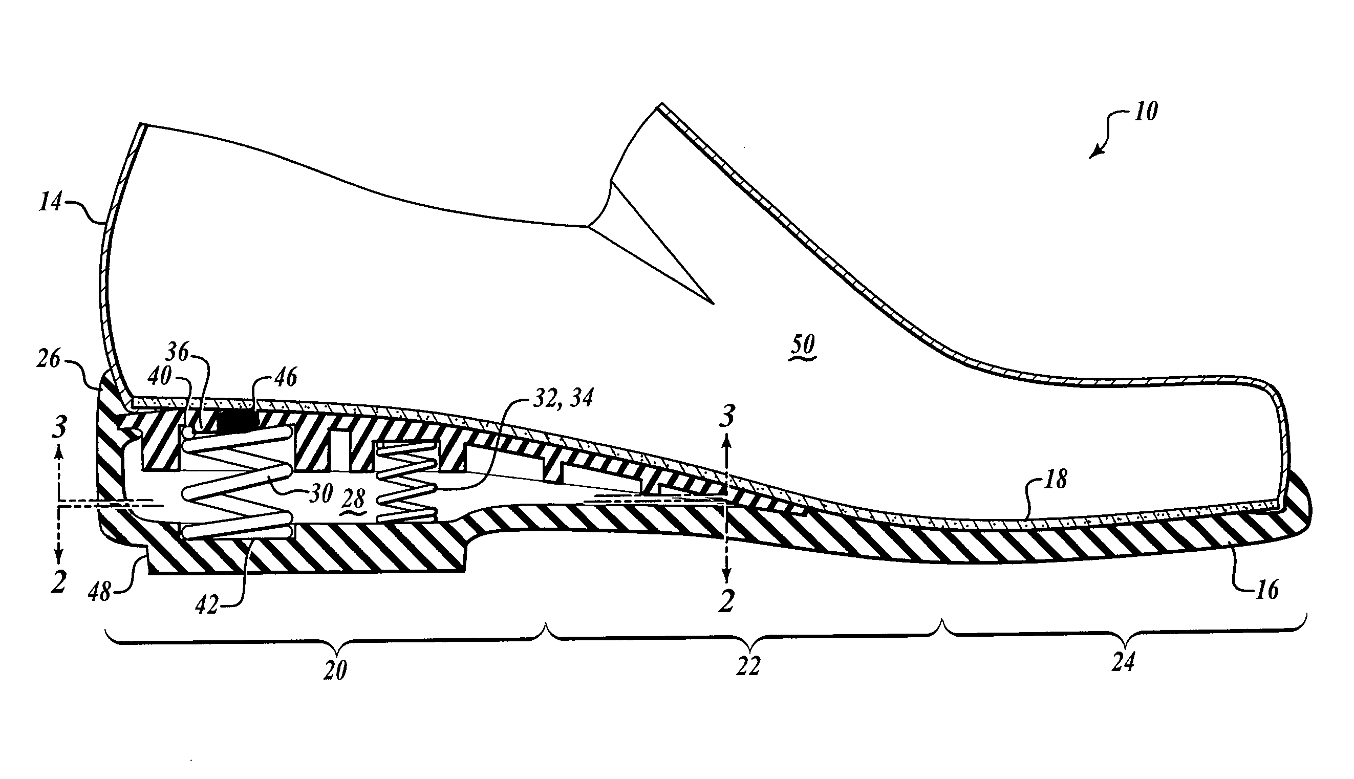
[0012]One embodiment of the invention includes a blended heel made from a resilient material and has a cavity extending under the entire instep portion of the shoe's upper. Compression springs are placed in the cavity, including a mainspring located at approximately the heelstrike point and two auxiliary springs for stability located forward of the mainspring toward the shoe's toe. The extended cavity provides even resiliency throughout the upper sole without having to resort to metal plates. The springs assist the resilient walls of the cavity, which extends under the instep portion of the shoe, in supporting the wearer's foot, and the spring's compression load is distributed throughout the sole by a resilient layer of softer rubber adjacent the sole.
[0013]The blended heel of the invention extends under the sole in a wedge-type configuration. This extension provides arch support and resiliency at the shoe's instep, or midsole. In one or more embodiments, the heel includes a height enhancer to provide lift without the appearance of “elevator shoes.” This pad located under the heel portion also serves to distribute the load of the springs and provides that the entire shoe is lifted, not just the wearer's foot.
[0014]In one embodiment, the springs include a mainspring and two smaller auxiliary springs in front of and evenly spaced to the inside and outside of the mainspring. The mainspring offers lift to the wearer reducing, if not eliminating, pressure on the wearer's spine, knees, and other joints. The auxiliary springs offer stability and additional absorption of the pressure forces generated from walking and other activity. In one or more embodiments, the springs are made from industrial grade aluminum spring material or many other suitable materials are within the scope of the invention. For example, instead of metallic springs, other spring members such as air balls or rubber balls could be used. The springs are aided by the resilient material itself that makes up the heel and the cavity walls.

Problems solved by technology

Conventional shoes do not allow the free flow of air throughout the inside of the shoe.
Moisture and bacteria build up inside most conventional shoes, causing athlete's foot and making such shoes smell.
The result is a shoe interior that will not be a breeding ground for odor-causing bacteria.

Method used


Image

  • Ventilated and resilient shoe apparatus and system
  • Ventilated and resilient shoe apparatus and system
  • Ventilated and resilient shoe apparatus and system

Examples


Embodiment Construction

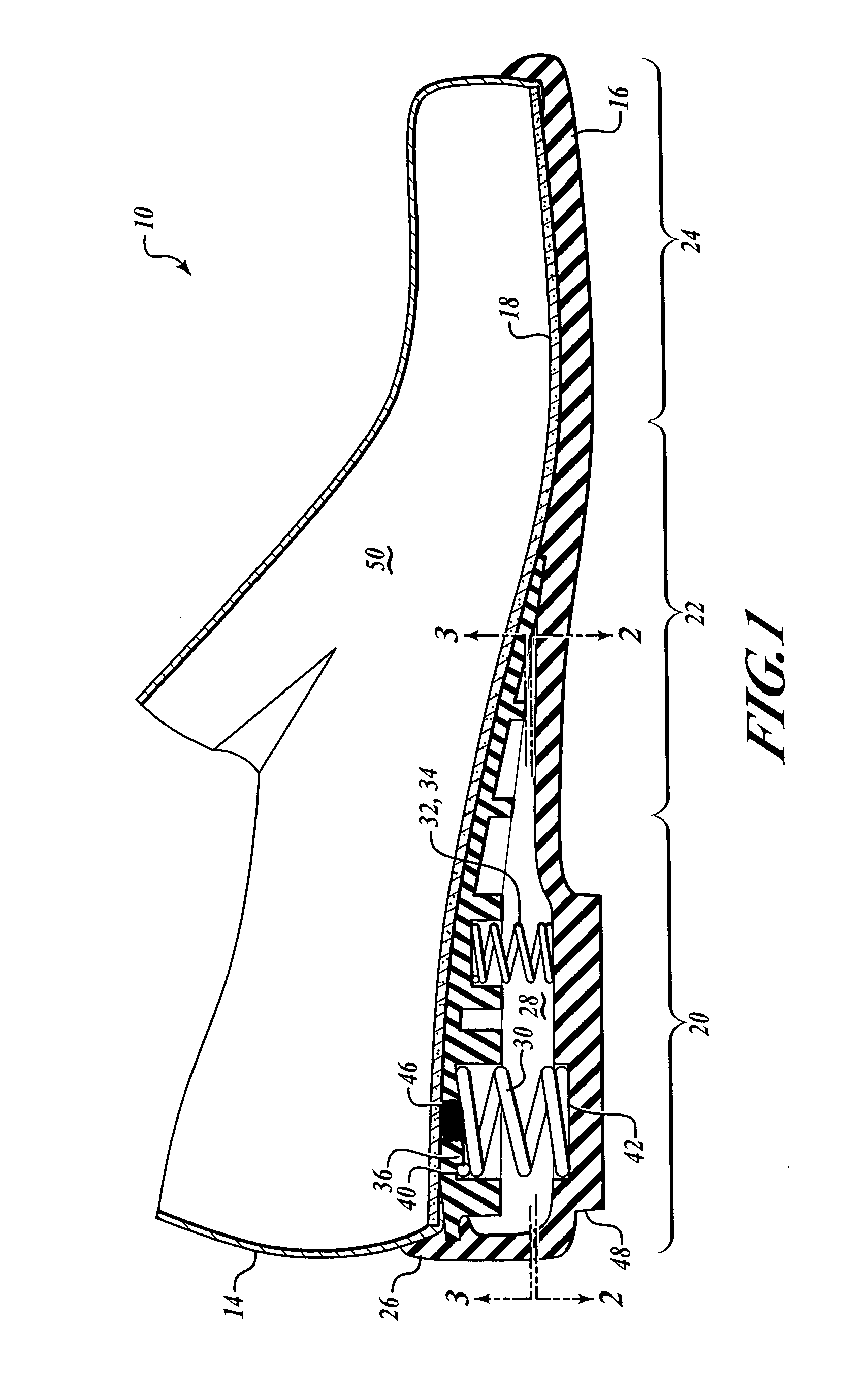
[0024]FIG. 1 shows an embodiment of the shoe 10 with upper 14 and lower 16 joined along the upper sole 18 extending through the heel portion 20, instep portion 22, and toe portion 24. The blended heel 26 defines a cavity 28 that extends from the rearmost point of the heel portion 20 forward under the instep portion 22. The blended heel 26 is made from a resilient material, typically rubber so the cavity walls offer some resiliency, but other resilient materials known to persons skilled in the art are within the scope of the present invention.

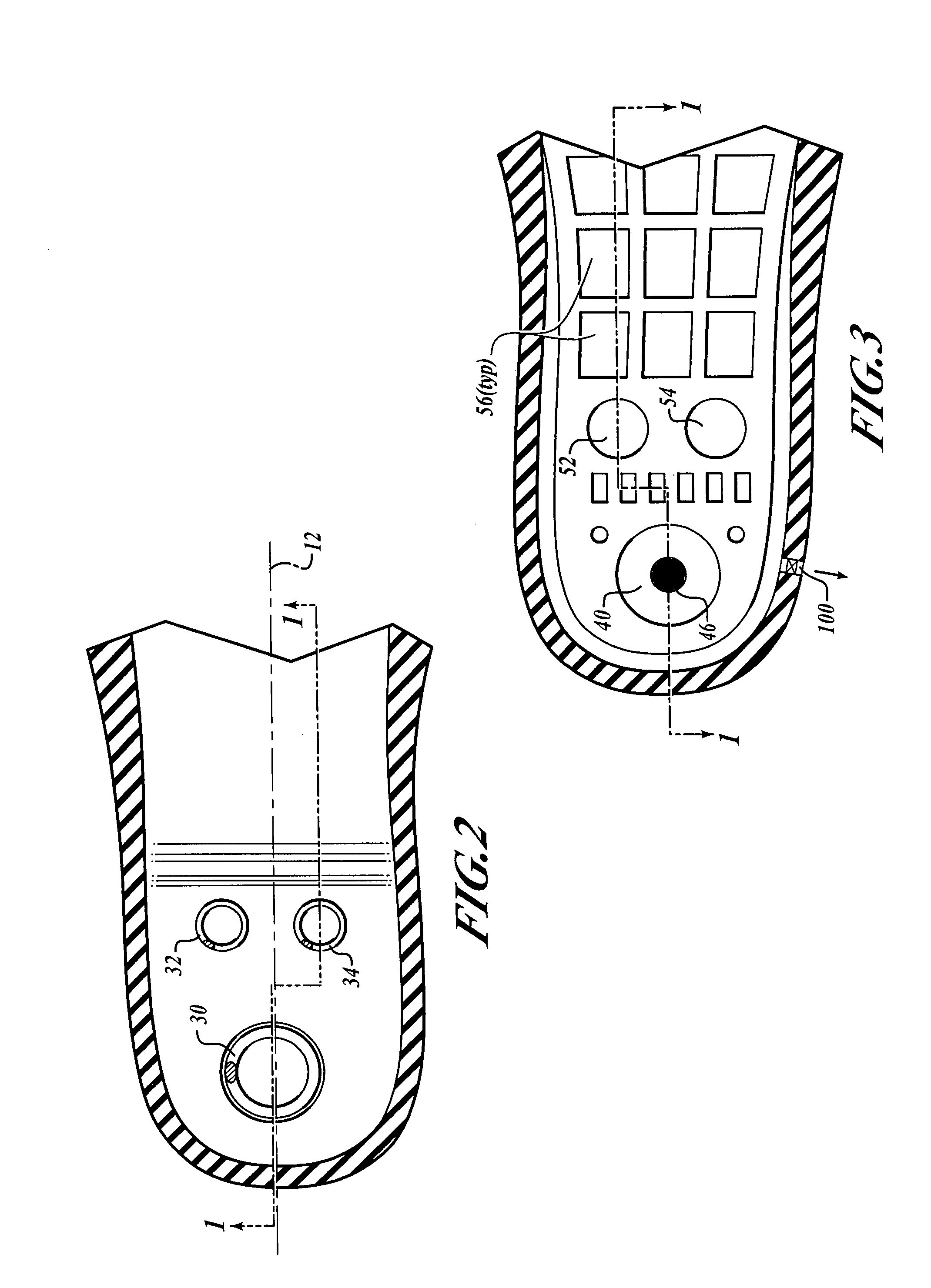
[0025]Two separate materials may be used, as is shown here, with the layer adjacent the upper sole of a softer material than the remainder of the heel. The mainspring 30 is positioned orthogonal to the longitudinal axis 12, as shown in FIG. 2, and under the heelstrike point of the interior of the shoe. The mainspring 30 may be secured by lugs 36 (upper) and 38 (lower; not shown) set into recesses 40 and 42, and provides the majority of resilient...


PUM

PropertyMeasurementUnit
lengthaaaaaaaaaa
resilientaaaaaaaaaa
areaaaaaaaaaaa

Abstract

An improved shoe includes an apparatus and system for ventilating inside the shoe and a resilient shoe. External air desirably enters the shoe around the wearer's foot and flows through holes in the sole into aeration chambers. The air circulates to the heel by a suction valve and is controllably directed out to the exterior of the shoe through a one-air air exhaust valve, ventilating the wearer's foot while an individual is walking. The heel is made from a resilient material and has a cavity extending under the entire instep portion of the shoe's upper. Compression springs are placed in the cavity, including a mainspring located at approximately the heelstrike point and two auxiliary springs for stability located forward of the mainspring toward the shoe's toe. The action of the springs is distributed throughout the sole by a resilient layer of softer rubber adjacent the sole to provide for a resilient walking experience.

Description

RELATED APPLICATION DATA[0001]The present application is related to and claims the benefit of U.S. Provisional Application No. 60 / 889,725 entitled “Shoe with Resilient Heel” filed Feb. 13, 2007, which is hereby incorporated by reference in its entirety.BACKGROUND OF THE INVENTION[0002]1. Field of the Invention[0003]This invention pertains generally to wearable articles for the feet and more particularly to shoes where air is circulated through the sole and heel and out via a one-way valve and has a resilient heel formed inside a shock-absorbing cavity.[0004]2. Description of the Related Art[0005]Conventional shoes are often uncomfortable. They do not allow the wearer to walk or stand for long because they do not provide any cushion or resiliency for the pressure put on the feet. This lack of cushion causes pressure to be felt in the spine, knees, and other joints. Heels with recesses and springs are not new; however, none of the prior art attempts successfully cushions the wearer's ...

Claims


Application Information

Patent Timeline
Patent Type & Authority Applications(United States)
IPC IPC(8): A43B1/00A43B13/00A43B13/20A43B7/06
CPCA43B1/0054A43B21/30A43B13/182A43B7/082
Inventor ELNEKAVEH, ALEXANDER
Owner ELNEKAVEH ALEXANDER
Learn More