Freight Handling Apparatus

a technology for handling equipment and cargo, applied in the field of cargo systems, can solve the problems of insufficient time and physical effort, insufficient labor intensity, and difficulty in filling orders in this manner, and achieve the effect of facilitating lifting and transporting, and facilitating transportation of the portable floor surfa

a technology for handling equipment and cargo, applied in the field of cargo systems, can solve the problems of insufficient time and physical effort, insufficient labor intensity, and difficulty in filling orders in this manner, and achieve the effect of facilitating lifting and transporting, and facilitating transportation of the portable floor surfa

US20080190917A1Inactive Publication Date: 2008-08-14MAGLINE

Image

  • Freight Handling Apparatus
  • Freight Handling Apparatus
  • Freight Handling Apparatus

Examples


Embodiment Construction

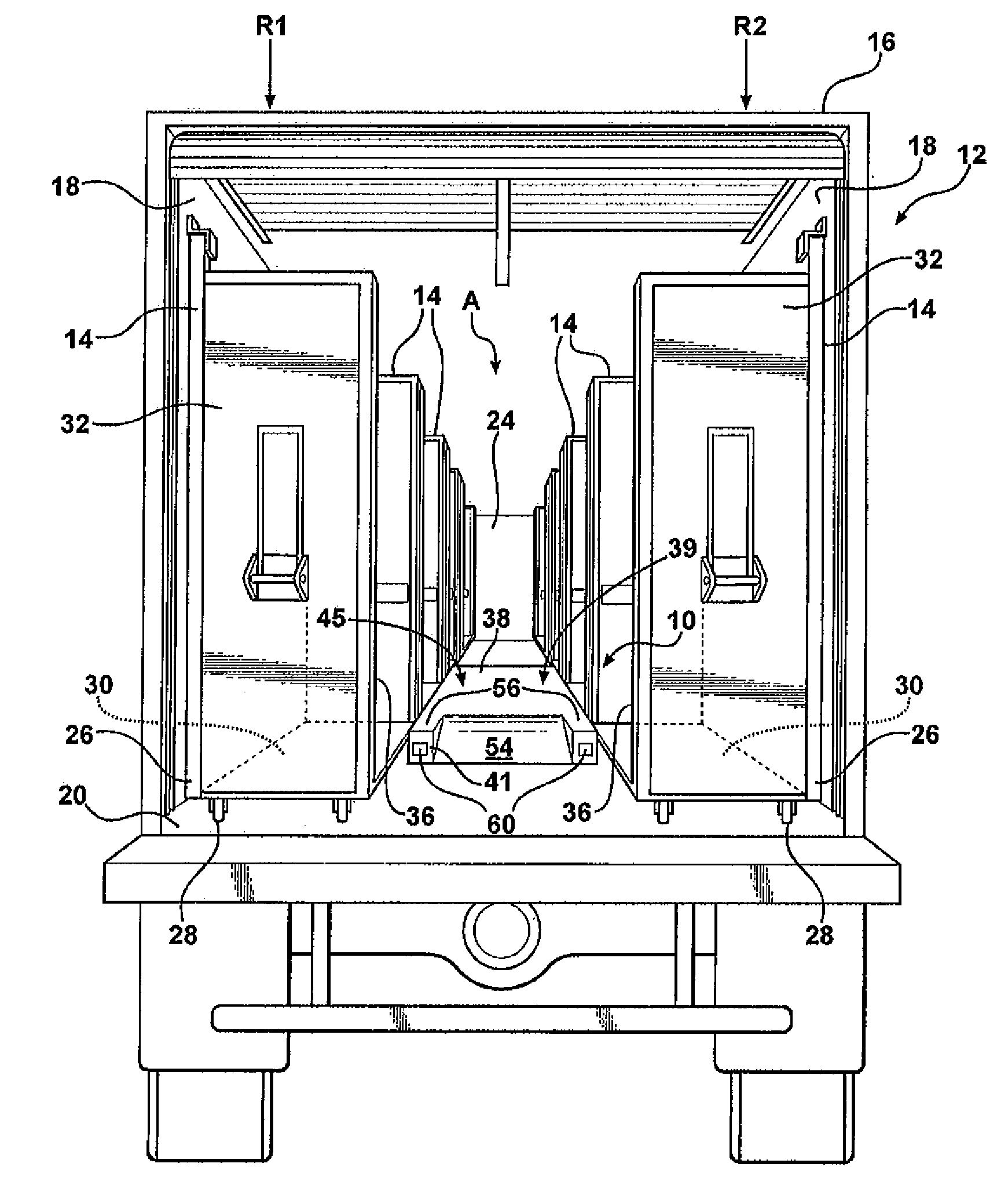
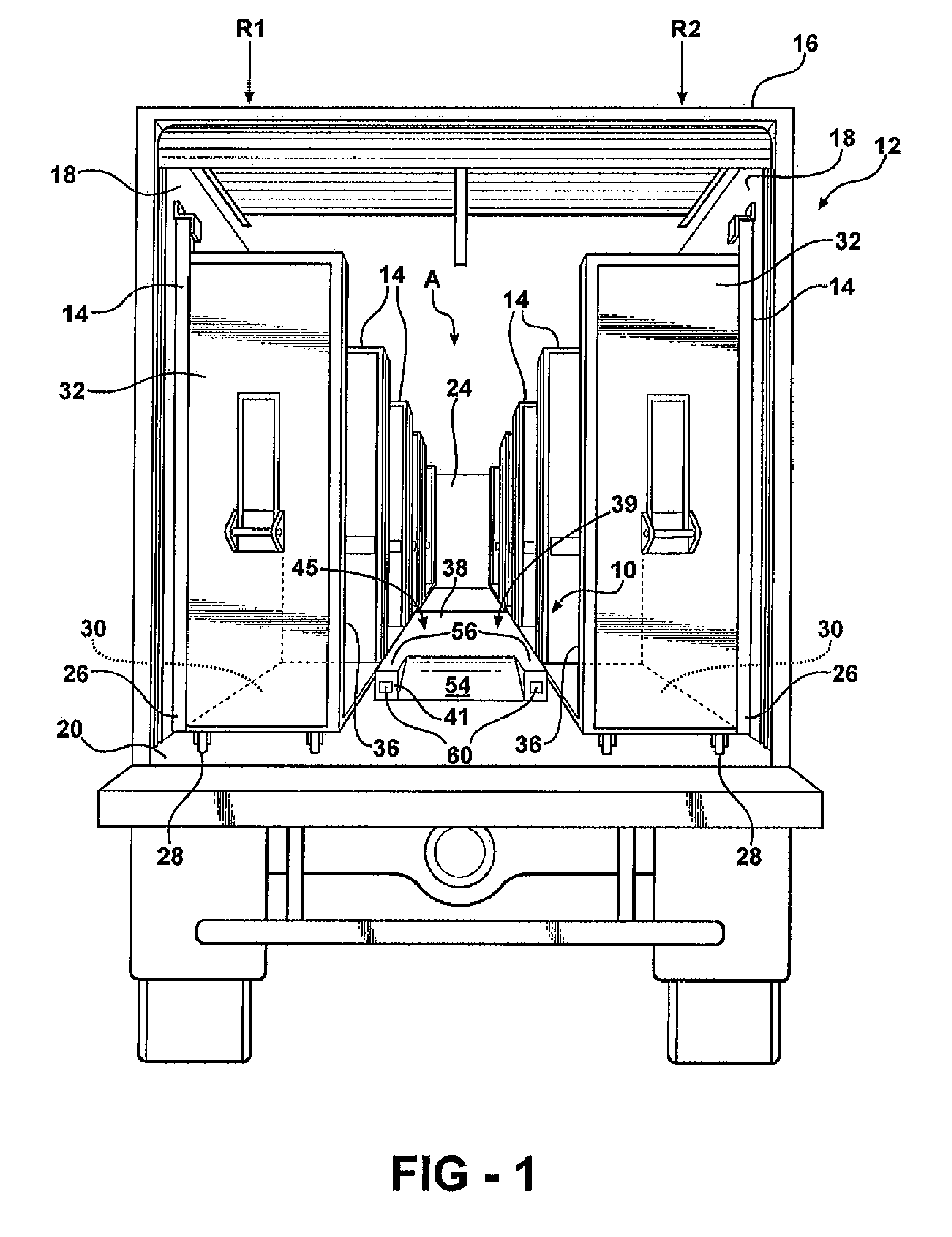
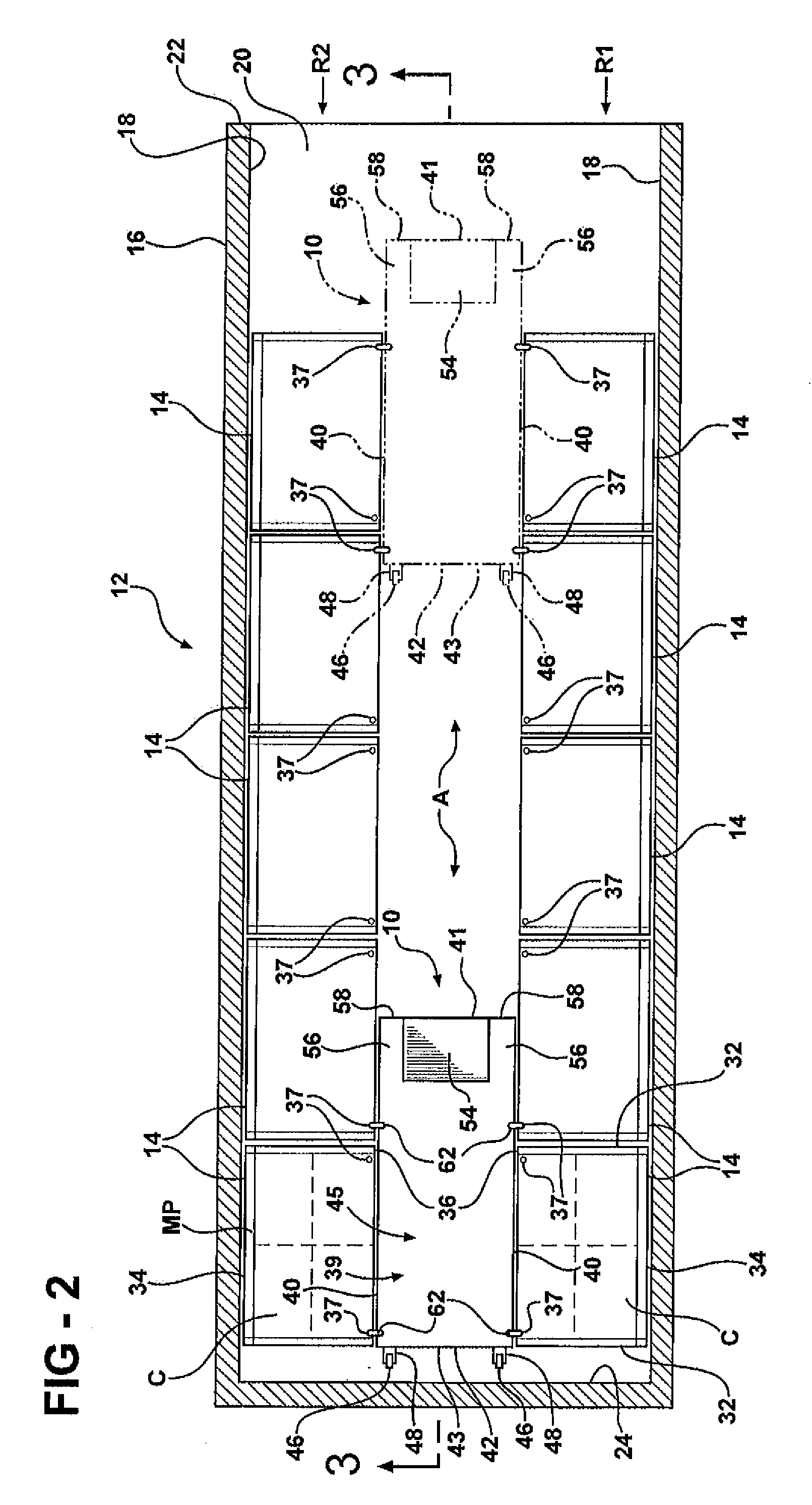
[0021]Referring in more detail to the drawings, FIGS. 1-5 illustrate a transport cart system or freight handling apparatus constructed according to one presently preferred embodiment having a portable floor surface, referred to hereafter as a platform or false floor 10. The false floor 10 is particularly suited for use with a product support and delivery system such as shown generally at 12 in FIGS. 1-4, and 5A, and disclosed in U.S. Pat. No. 6,520,515 to Krawczyk, incorporated herein by reference in its entirety, and which is assigned to Magline, Inc., the assignee of applicants' invention herein. In one aspect, the system 12 includes a plurality of wheeled modules, containers, or carts 14 that can be positioned side-by-side within an interior of a transportation vehicle, such as an enclosed trailer or van 16, for example. The carts 14 are preferably positioned on a floor 20 along opposite sidewalls 18 of the van 16 in longitudinally extending rows R1, R2 (FIGS. 1 and 2). The rows ...


PUM


Abstract

A freight handling apparatus includes at least one of a container or a platform. The container has a front to receive freight and a first retaining feature disposed at the front. The platform has a side that may be laterally opposed to the front of the container and a second retaining feature disposed at the side. The platform retaining feature may cooperate with the container retaining feature to releasably retain the platform to the container.

Description

CROSS-REFERENCE TO RELATED APPLICATIONS[0001]This application claims the benefit of and incorporates herein by reference in its entirety U.S. Provisional Application Ser. No. 60 / 633,929, filed Dec. 7, 2004, and is a continuation-in-part of U.S. application Ser. No. 11 / 295,795, filed Dec. 7, 2005, which is incorporated herein by reference in its entirety.FIELD OF THE INVENTION[0002]This invention relates generally to freight systems for freight carriers and, more particularly, to a freight handling apparatus to be transported in a freight carrier.BACKGROUND OF THE INVENTION[0003]A system which is presently commonly used to handle and transport cases of beverage containers, for example, from a manufacturing and / or distributing center to a retailer, such as a grocery store, convenience store, etc., is inherently a laborious, time-consuming operation requiring numerous delivery vehicles and operators, each covering a rather limited region. The traditional system involves stacking large ...

Claims


Application Information

Patent Timeline
14 Aug 2008
Publication
US20080190917A1
IPC
B65D88/00; B65D19/44
CPC
B60P3/055; B65G69/30; B60P7/13
Inventors
FRAHM, JEFFRY R.