Tire curing metal mold and tire manufacturing method

a metal mold and tire technology, applied in the field of tire curing metal mold and tire manufacturing method, can solve the problems of uneven tread surface, uneven gap, uneven tread, etc., and achieve the effects of reducing clearance, preventing attrition and galling of the piece, and preventing the overflow of rubber

Inactive Publication Date: 2008-08-14
TOYO TIRE & RUBBER CO LTD
View PDF8 Cites 18 Cited by
  • Summary
  • Abstract
  • Description
  • Claims
  • Application Information

AI Technical Summary

Benefits of technology

[0029]Thereafter, the uncured tire is set within the mold (the setting step), the mold is clamped, the curing step is carried out by bringing the annular mold portion into contact with the tread surface of the tire (the curing step), and the cured tire is detached from the mold by opening the mold (the mold detaching step). The series of steps mentioned above are carried out in the state in which the tire curing metal mold is in the heated state and the magnitude of the gap between the pieces is defined. Since the gap between the pieces in this stage can be suitably adjusted by taking into consideration the clearance in the unheated state, the coefficients of thermal expansion of the piece and the back segment and the like, it is possible to secure the air discharge while preventing the overflow of the rubber.
[0030]After the mold detaching step, the tire cur

Problems solved by technology

Further, at a position where the gap is too small, an air existing between the inner circumferential surface of the sector and the tread surface is not properly discharged, and a shrink called as lights is generated.
However, in the tire curing metal molds, since each of the pieces slides in the tire circumferential direction every opening and closing mot

Method used


Image

  • Tire curing metal mold and tire manufacturing method
  • Tire curing metal mold and tire manufacturing method
  • Tire curing metal mold and tire manufacturing method

Examples


Embodiment Construction

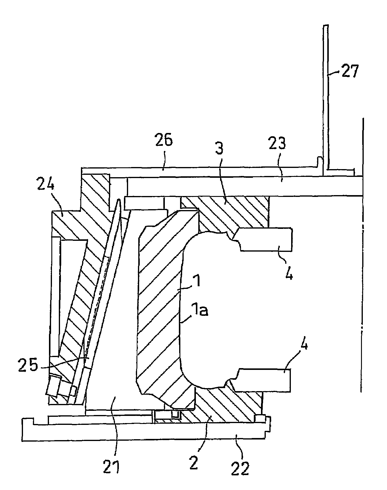
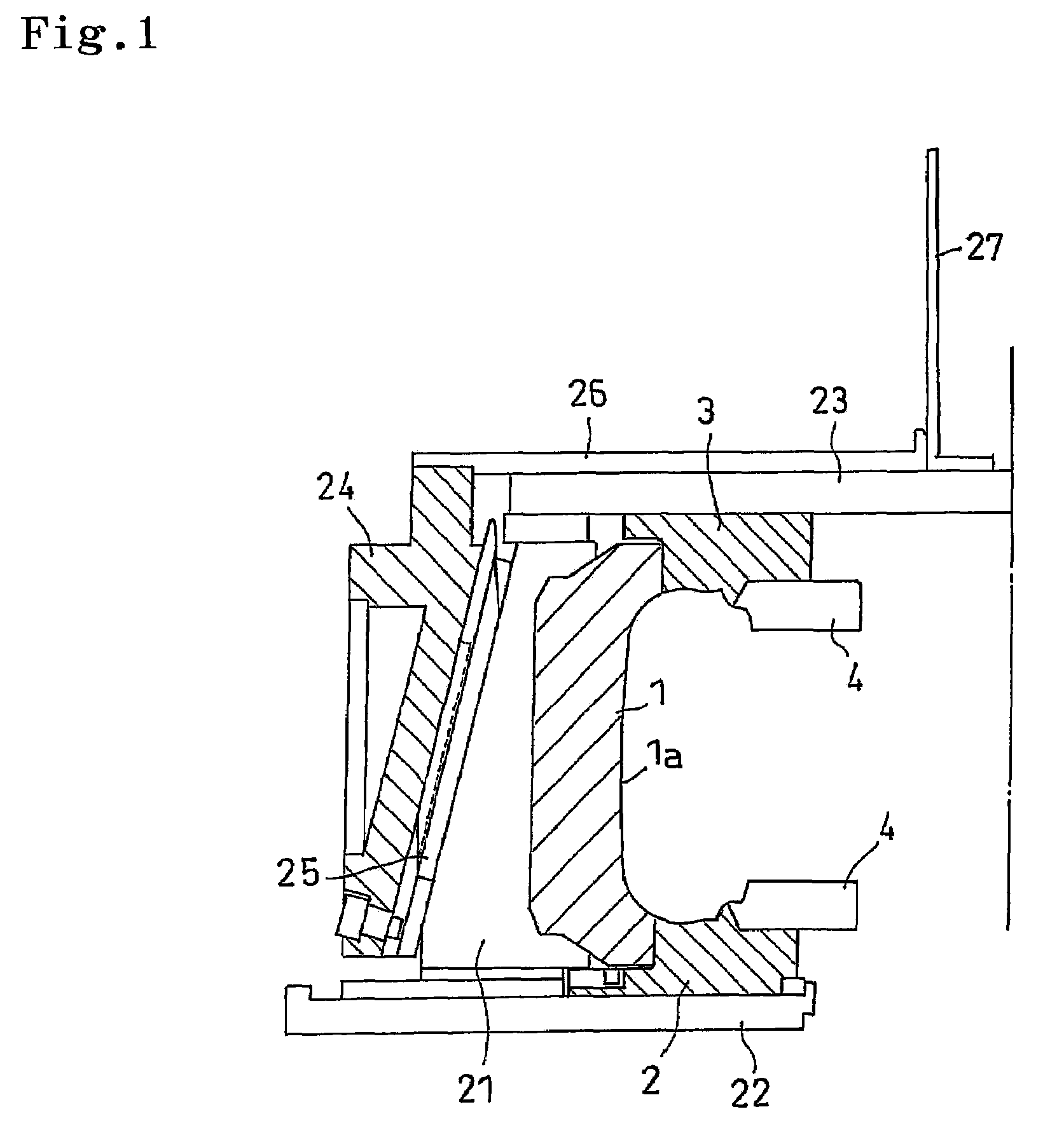
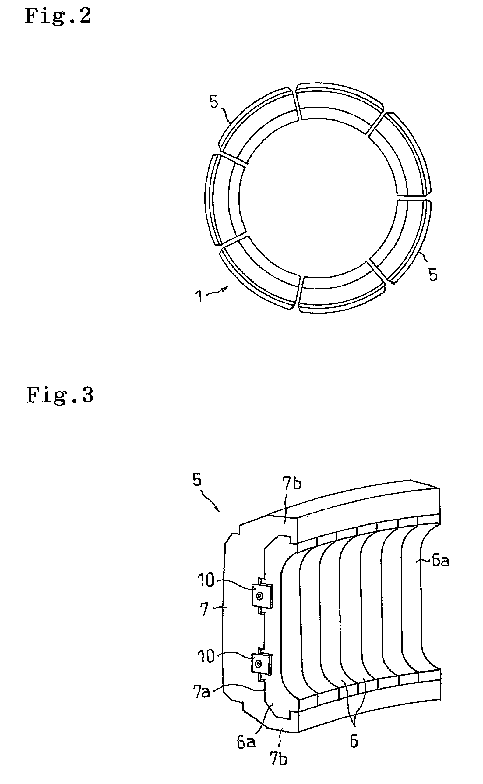
[0039]An embodiment of the present invention will be explained with reference to the drawings. FIG. 1 is a vertical cross sectional view schematically showing an example of a tire curing metal mold in accordance with the present invention, and shows a mold clamping state. In the drawing, an uncured tire (not shown) is set in such a manner that a tire axial direction is arranged up and down. In other words, a vertical direction in FIG. 1 corresponds to a tire width direction, a right direction corresponds to an inner side in a tire diametrical direction, and a left direction corresponds to an outer side in the tire diametrical direction. FIG. 2 is a plan view of an annular mold portion provided in the tire curing metal mold.

[0040]The tire curing metal mold is a segmented mold provided with an annular mold portion 1 with which a tread surface of a tire is brought into contact, a lower mold portion 2 with which a side wall portion in a lower side is brought into contact, and an upper m...


PUM

PropertyMeasurementUnit
Widthaaaaaaaaaa
Coefficient of linear thermal expansionaaaaaaaaaa
Thermal expansion coefficientaaaaaaaaaa

Abstract

A sector is provided with a plurality of pieces divided in a tire circumferential direction, a back segment supporting a plurality of pieces, and an elastic body interposed between end surfaces in the tire circumferential direction of the pieces. In an unheated state before curing, since clearances C1 to C3 are provided between the piece and the back segment, and the piece is slidable in the tire circumferential direction, it is possible to suitably adjust a gap between the pieces to a uniform state without any deviation. Further, in a heated state at a time of curing, since the clearances C1 to C3 are reduced by a thermal expansion of the piece, and the piece is fixed to the back segment, the piece does not slide in the tire circumferential direction, and it is possible to prevent an attrition and a galling of the piece from being generated early.

Description

BACKGROUND OF THE INVENTION[0001]1. Field of the Invention[0002]The present invention relates to a tire curing metal mold for curing a tire, and a tire manufacturing method using the tire curing metal mold.[0003]2. Description of the Related Art[0004]A tire curing metal mold for curing a tire is structured by combining a plurality of mold portions, and is broadly classified into a two-piece type and a segmented type on the basis of a division aspect. In the latter, an annular mold portion brought into contact with a tread surface of the tire is structured by a plurality of sectors divided in a tire circumferential direction, and an inner peripheral surface of each of the sectors is provided with a bone portion for forming a groove portion, and a concave portion for forming a land portion comparted by the bone portion. The respective sectors are spaced from each other in a mold opened state, and get together in a mold clamp state so as to form an annular shape.[0005]In this case, in ...

Claims


Application Information

Patent Timeline
IPC IPC(8): B29C41/46B29C35/02
CPCB29C33/302B29D30/0606B29D2030/0653B29D2030/0631B29D30/0629
Inventor HYODO, MASAKI
Owner TOYO TIRE & RUBBER CO LTD
Why Eureka
Try Eureka