AI technical title is built by Patsnap AI team. It summarizes the technical point description of the patent document.
a technology of torsion bar and twist beam, which is applied in the field of twist beam axle, can solve the problems of low shear center of such twist beam, relatively expensive twist beam, and known twist beam with separate torsion bar
Inactive Publication Date: 2008-08-14
MAGNA INTERNATIONAL INC
View PDF23 Cites 24 Cited by
Summary
Abstract
Description
Claims
Application Information
AI Technical Summary
This helps you quickly interpret patents by identifying the three key elements:
Problems solved by technology
Method used
Benefits of technology
Benefits of technology
The invention is a twist beam axle assembly with a torsion member attached to the twist beam. The twist beam has an open cross-sectional configuration with bight portions and projections, and the torsion member is securely attached to the bight portion. The assembly also includes arms and wheel hubs for attaching to the twist beam. The method of forming the assembly involves roll forming the twist beam and seam welding the torsion member to it. The technical effects of this invention include improved load bearing capacity, reduced weight, and improved efficiency of the axle assembly.
Problems solved by technology
Known twist beams with separate torsion bars are relatively expensive and the shear center of such twist beams is relatively low.
However, these twist beams are relatively expensive to manufacture.
Method used
Image
Click on the blue label to locate the original text in one second.
Reading with bidirectional positioning of images and text.
Examples
Embodiment Construction
[0020]FIGS. 1-5 illustrate one embodiment of the present invention. FIG. 1 illustrates a twist beam rear axle assembly 10 of a motor vehicle. As seen in dashed lines, the assembly 10 is attached to a space frame 12 of the motor vehicle as generally known in the art.
[0021]Assembly 10 basically includes a twist beam 14 and two side arm assemblies 16 and 18. The twist beam 14 extends between the side arm assemblies 16 and 18 with a side arm assemblies 16 and 18 coupled to respective ends 20 and 22 of the twist beam 14. Each side arm assembly 16 and 18 includes a side arm 24 and 26, respectively, which is directly attached to the twist beam 14. The remaining illustrated parts for each of the side arm assemblies 16 and 18 are substantially identical for each side arm assembly 16 and 18. That is, each side arm assembly 16 and 18 includes, among other things, a wheel hub 30 and wheel hub mount 32, a spring seat 34, a shock absorber 36 and a bushing connection 38. Each side arm assembly 16 ...
PUM
Property
Measurement
Unit
thickness
aaaaa
aaaaa
thickness
aaaaa
aaaaa
resistance
aaaaa
aaaaa
Abstract
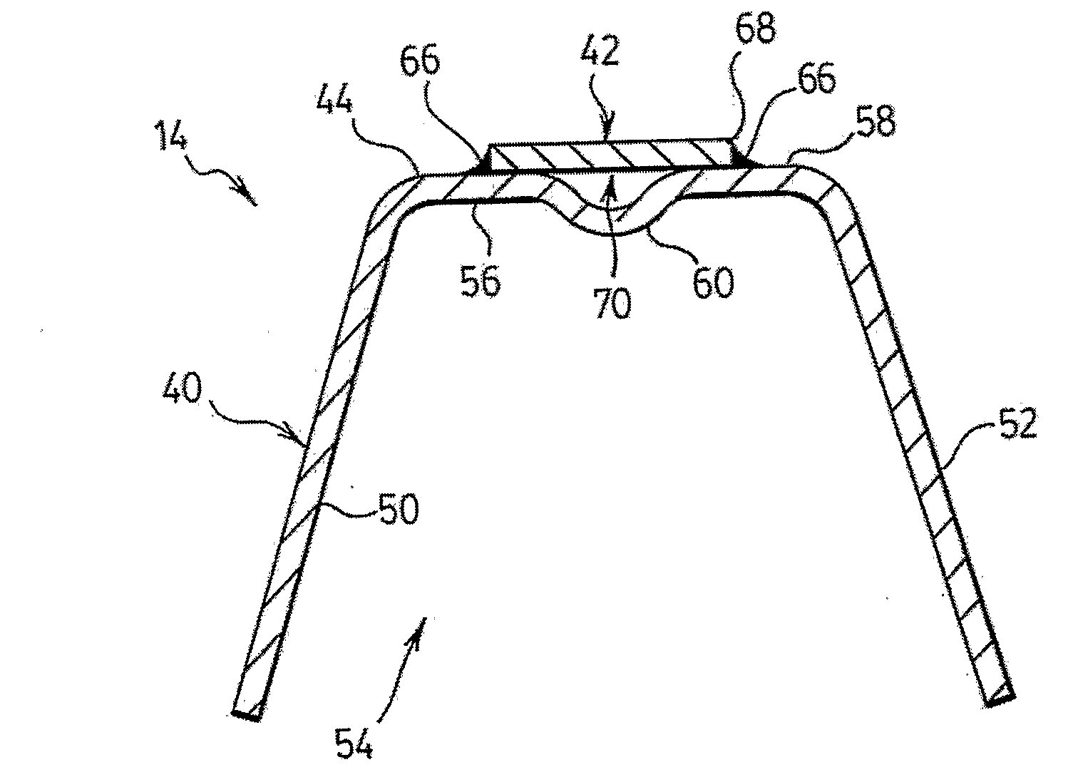
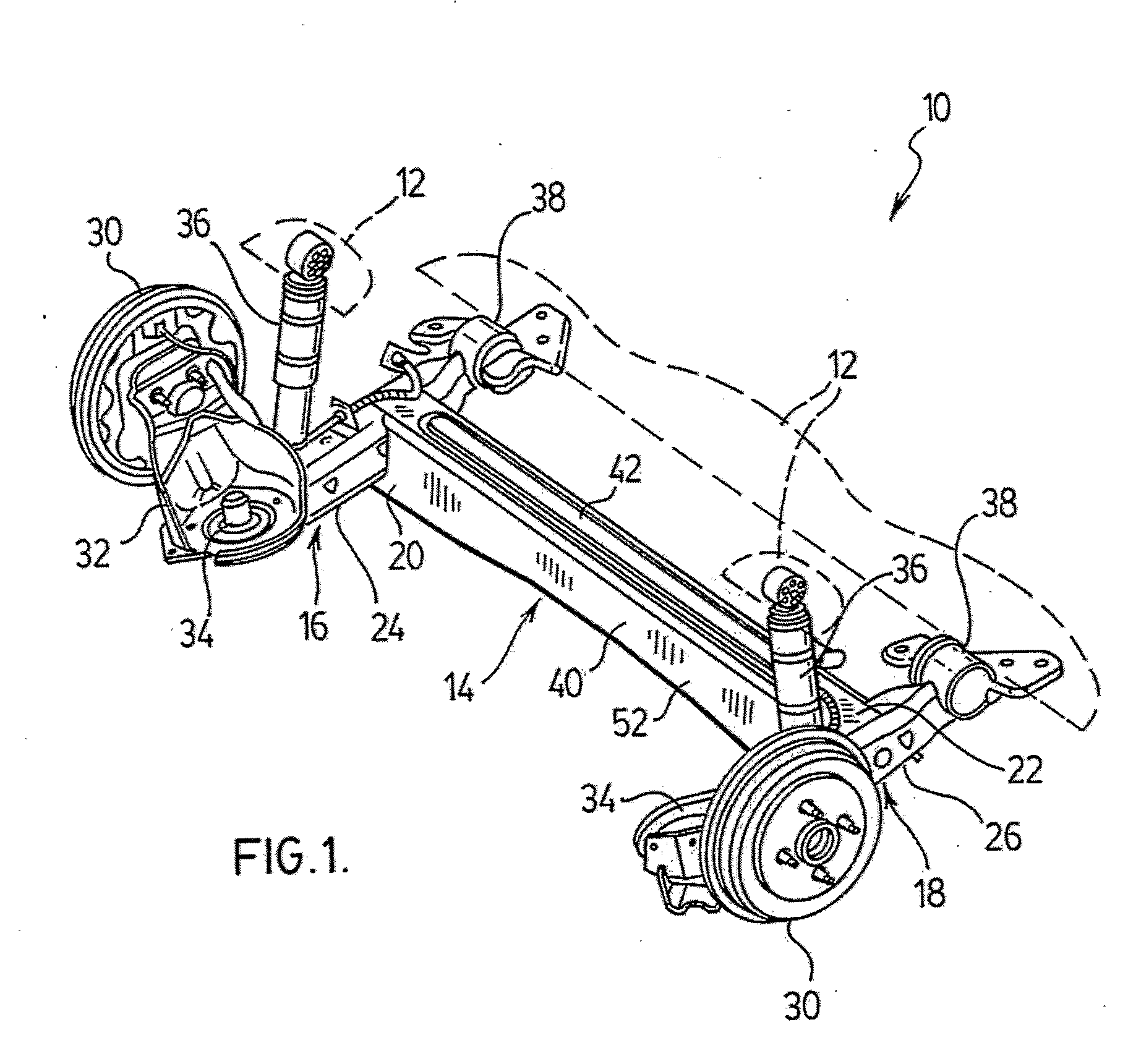
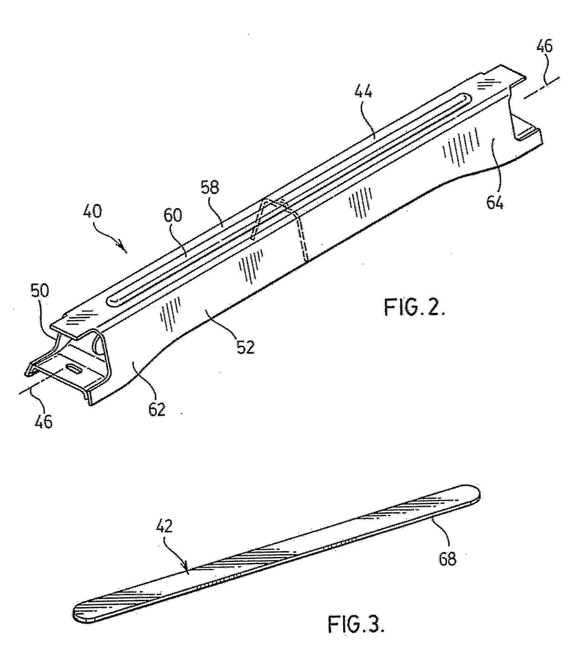
A traditional twist beam axle found in a vehicle includes a twist beam with a separate torsion beam or a hollow tube formed into an inverted U shape that acts as both the twist beam and the torsion beam. Both solutions are expensive to manufacture A twist beam axle (14) is provided wherein the torsion member (42) is rigidly secured to the twist beam (40) The twist beam (40) has a U-shaped cross-sectional configuration having a bight portion (44) with first (50) and second (52) projections extending therefrom Embodiments include the cross-sectional configuration having an open cavity and the bight portion (44) having an indentation into the open cavity and forming a depression that is covered by the torsion member (42) A method of forming the disclosed twist beam axle (14) is also provided, the method including the step of rigidly securing the torsion member (42) to the bight portion (44) of the twist beam (40)
Description
FIELD OF THE INVENTION[0001]The present invention relates to twist beams. More specifically, the present application illustrates embodiments of the present invention, including embodiments relating to a vehicle twist beam axle.BACKGROUND OF THE INVENTION[0002]U.S. Pat. Nos. 6,616,157 to Christophliemke et al.; 6,401,319 to Hicks et al.; 5,520,407 to Alatalo et al.; 5,518,265 to Buthala et al.; 5,409,254 to Minor et al.; and 5,246,248 to Ferguson et al. each disclose a vehicle rear suspension apparatus. The rear suspension apparatus commonly includes a cross beam that includes a twist beam and a separate torsion beam to provide bending and torsional stiffness. Known twist beams with separate torsion bars are relatively expensive and the shear center of such twist beams is relatively low.[0003]In other twist beams, such as described in U.S. Pat. Nos. 5,324,073 to Alatalo et al.; 5,409,255 to Alatalo et al; 5,518,265 to Buthala et al.; 5,520,407 to Alatalo et al.; 6,059,314 to Streubel...
Claims
Application Information
Patent Timeline
Application Date:The date an application was filed.
Publication Date:The date a patent or application was officially published.
First Publication Date:The earliest publication date of a patent with the same application number.
Issue Date:Publication date of the patent grant document.
PCT Entry Date:The Entry date of PCT National Phase.
Estimated Expiry Date:The statutory expiry date of a patent right according to the Patent Law, and it is the longest term of protection that the patent right can achieve without the termination of the patent right due to other reasons(Term extension factor has been taken into account ).
Invalid Date:Actual expiry date is based on effective date or publication date of legal transaction data of invalid patent.
Patent Type & AuthorityApplications(United States)

