Wind-driven electricity generation device with savonius rotor

a wind-driven, electricity generation technology, applied in the direction of electric generator control, renewable energy generation, greenhouse gas reduction, etc., can solve the problems of large unitary blade pair, heavy weight and unwieldy handling and installation, and limited use of drag-type rotors by few people. achieve the effect of convenient completion

Inactive Publication Date: 2008-08-14
SAUER ENERGY +1
View PDF55 Cites 64 Cited by
  • Summary
  • Abstract
  • Description
  • Claims
  • Application Information

AI Technical Summary

Benefits of technology

[0009]Assembly of the device is uniquely simple. A simple base structure is assembled, usually from common struts, and the generator device and shaft bearings are mounted on the base structure. The vertical shaft is then inserted through the bearings and into operable contact with the generator. Finally, each blade pair segment is slid onto the sh...

Problems solved by technology

While there have been many designs proposed or used for the wind-driven vertical rotors which drive the generators, very few have used Savonius drag-type rotors.
The inclusion of unitary blade pairs in any size other than the very smallest in such devices severely limits the devices use in many environments and for many uses becaus...

Method used


Image

  • Wind-driven electricity generation device with savonius rotor
  • Wind-driven electricity generation device with savonius rotor
  • Wind-driven electricity generation device with savonius rotor

Examples


Embodiment Construction

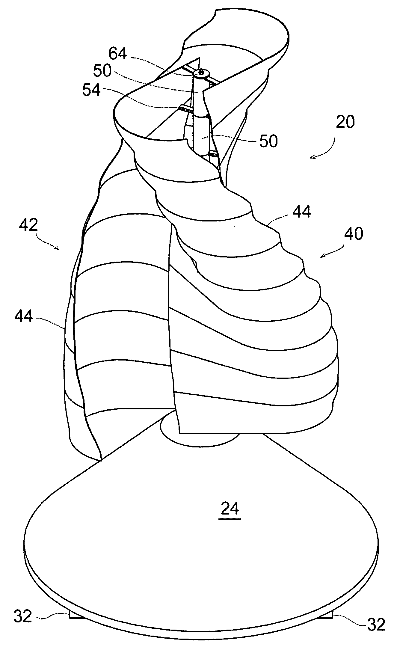
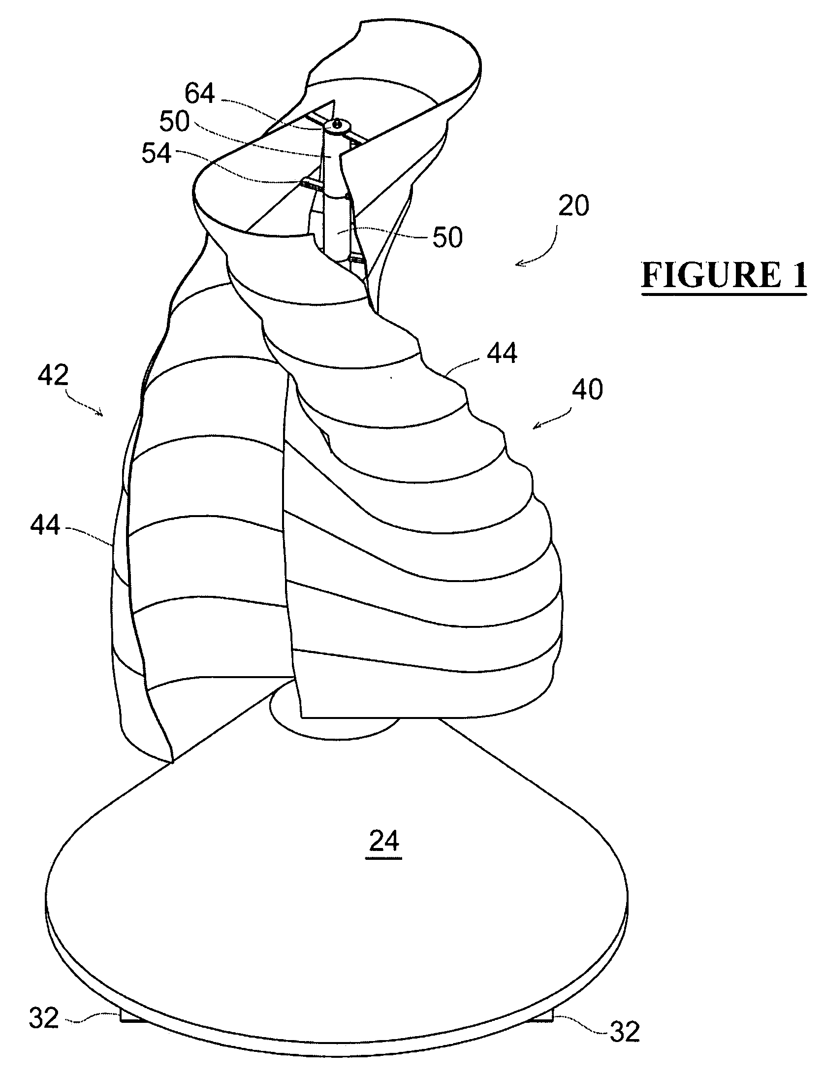
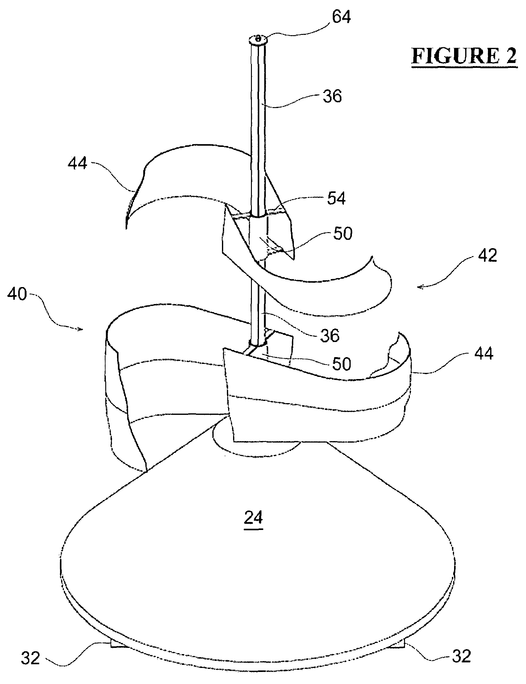
[0020]The invention will be best understood by reference to the drawings, particularly FIGS. 1, 2 and 8. In the embodiment illustrated the device 20 has a base 22 which for appearance may be covered by a cone shaped skirt 24. Included in the base 22 structure are shaft bearings 26 and 28. Supporting struts 30 are disposed radially around the base 22, are attached thereto at their top ends, and extend diagonally downward. While for clarity only two of the of the supporting struts 30 are shown in FIG. 8, it will be evident that full support of the device will require at least three such struts and preferably four to eight struts. Normally the struts will be disposed equally spaced around the base 22 of the device, although unequal spacing may be desirable if the device is to be installed on particularly uneven ground. The struts 30 will be attached at their lower ends to ground contact structure 32 which may be in the form of a circular or polygonal flat panel or may be made up of rad...


PUM

PropertyMeasurementUnit
Angleaaaaaaaaaa
Heightaaaaaaaaaa
Heightaaaaaaaaaa

Abstract

A vertical wind-driven electricity generation device is described, which utilizes a unique segmented Savonius rotor and which is easily handled, transported, assembled and maintained, even by a single person. The blades of the rotor are segmented into a plurality of modest size blade pair segments, each of which comprises two (or optionally, three or four) low height, helically curved blade portions. The blade pair segments are preferably of the same height and diameter. The rotor is mounted on a central vertical shaft connected to a generator. When the plurality of blade portions are installed on the device's central shaft, the overall blade configuration functions as an unitary Savonius rotor. Flow of gas (normally air in the form of wind) causes the segmented Savonius rotor to move, turning the shaft and rotating member of the generator to rotate, causing the generator to generate electricity.

Description

FIELD OF THE INVENTION[0001]This invention relates to electric power generators and segmented rotors. More particularly it relates to electric power generators which are driven by wind energy through a segmented Savonius rotor and can be used in small installations such as individual residential installations.BACKGROUND OF THE INVENTION[0002]Wind-powered or wind-driven electricity generation devices, are a significant source of renewable electrical energy. Some are aligned horizontally, mounted on tall masts and resembling large propeller-equipped aircraft engines, and others are vertically aligned and equipped with two or more elongated vertical sail-like rotors. The present invention involves the latter group. While there have been many designs proposed or used for the wind-driven vertical rotors which drive the generators, very few have used Savonius drag-type rotors. It has been believed that lift-type rotors were more efficient for large scale devices, and Savonius rotors have ...

Claims


Application Information

Patent Timeline
IPC IPC(8): F03D9/00
CPCF03D3/005F03D3/061F05B2240/213Y10T29/49002F05B2250/25Y02B10/30Y02E10/74F05B2240/40
Inventor MORGAN, KENSLATTERY, MICHEAL
Owner SAUER ENERGY
Why Eureka
Try Eureka