Discharge lamp

Inactive Publication Date: 2008-08-14
PANASONIC CORP
View PDF1 Cites 2 Cited by
  • Summary
  • Abstract
  • Description
  • Claims
  • Application Information

AI Technical Summary

Benefits of technology

[0028]According to the discharge lamp having the above structure, the adjacent parts within the glass tube, each of which is adjacent to one of the bases, are fixed at least to the bases by a fixation material). Therefore, even if tensile load is applied to the discharge lamp when attached to and detached from a lamp fitting, deformation of the glass tube can be efficiently prevented. Consequently, it is possible to realize a discharge lamp less likely to be broken when attached to and detached from a lamp fitting. On the other hand, in order to realize the above-mentioned object, the discharge lamp of the third present invention comprises: an arc tube (i) which includes a glass tube and electrodes each disposed at one of two end parts of the glass tube, and (ii) in which a portion of the glass tube, extending from a middle part of the glass tube to one of at least one end part and at least one end-part neighboring part thereof, winds around an imaginary axis and progressively away from the imaginary axis as shifted in a direction from the middle part towa

Problems solved by technology

However, with the arc tube of such a flat double spiral discharge lamp, there is a problem that the arc tube has a greater tendency to be broken during the discha

Method used


Image

  • Discharge lamp
  • Discharge lamp
  • Discharge lamp

Examples


Example

[0055]The following describes a preferred embodiment of a discharge lamp according to the present invention with reference to drawings.

[0056]1. Structures of Discharge Lamp

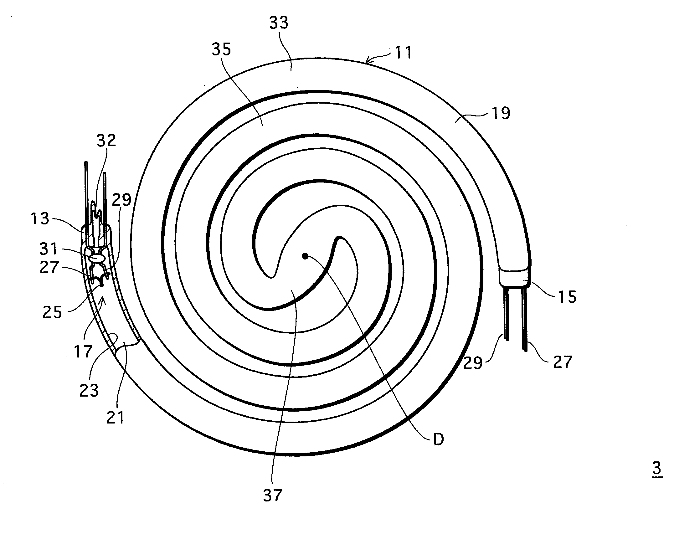
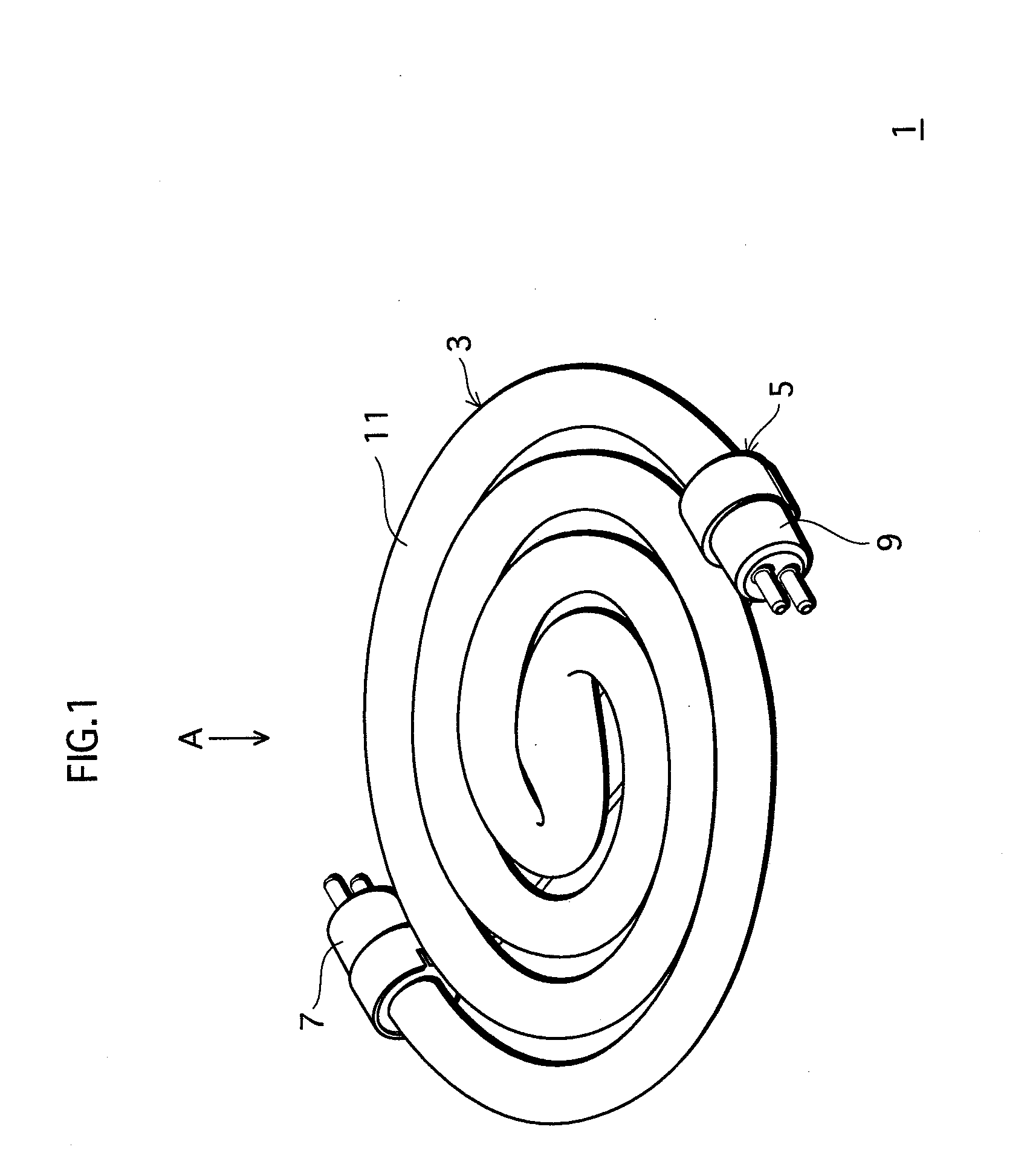
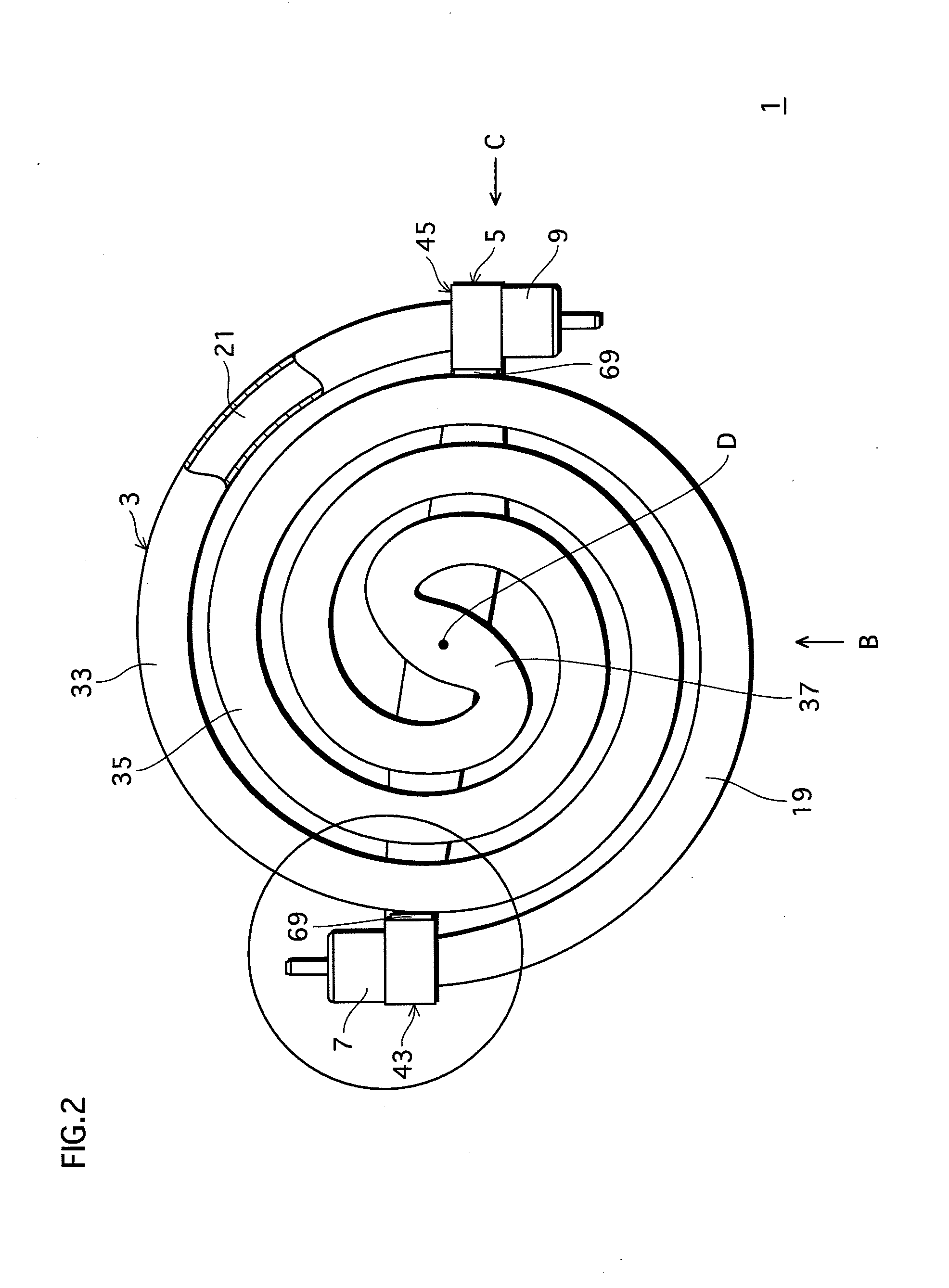
[0057]FIG. 1 is a perspective view of a discharge lamp of the embodiment. FIGS. 2 and 3 are a plan view and a bottom view, respectively, of the discharge lamp. FIGS. 4 and 5 are an elevation view and a lateral view, respectively, of the discharge lamp.

[0058]Here, the plan view of a discharge lamp 1 (FIG. 2) is a diagram where the discharge lamp 1 fitted to a lamp fitting is viewed from an irradiated plane (see FIG. 4). That is, the diagram provides a view of the discharge lamp 1 seen from the upper side in FIG. 1 (Direction A in the figure). The elevation view of the discharge lamp 1 (FIG. 4) is a diagram of the discharge lamp 1 viewed from the lower side in FIG. 2 (Direction B in the figure); the lateral view of the discharge lamp 1 (FIG. 5) is a diagram of the discharge lamp 1 viewed from the lateral side in FIG...


PUM


Abstract

The discharge lamp comprises: an arc tube including electrodes disposed at both ends of a glass tube; and bases provided at the two ends of the glass tube and supplying power to the electrodes. The arc tube includes two spiral parts, extending from the middle part of the glass tube to both end parts thereof, circularly winding around an imaginary axis and progressively away from the imaginary axis as shifted in a direction from the middle part toward the end parts. The end parts of the glass tube are attached by a silicon resin to adjacent parts of the glass tube, which are located on the imaginary axis side in relation to the end parts.

Description

[0001]This application is based on application No. 2007-032625 filed in Japan, the contents of which are hereby incorporated by reference.BACKGROUND OF THE INVENTION[0002](1) Field of the Invention[0003]The present invention relates to a discharge lamp including an arc tube in which (i) electrodes are disposed at both ends of a glass tube and (ii) a portion of the glass tube, extending from the middle part of the glass tube to at least one end part, or part before and adjoining to the end part, winds around an imaginary axis and progressively away from the imaginary axis as shifted in the direction from the middle part toward the at least one end part, or the part before and adjoining to the end part.[0004](2) Related Art[0005]As a discharge lamp used for common lighting, circular tube discharge lamp is widely known which uses a circle-shaped arc tube formed by bending a straight bulb into a circular shape. With such circular tube discharge lamp, in recent years, there is an increas...

Claims


Application Information

Patent Timeline
IPC IPC(8): H01J1/62
CPCH01J5/565H01J61/322H01J5/58
Inventor ITAYA, KENJIKAKUNO, YOSHINORIKATASE, KOUICHITAKAHASHI, JUN'ICHI
Owner PANASONIC CORP
Why Eureka
Try Eureka