Stereoscopic Image Display Apparatus, Stereoscopic Image Displaying Method And Computer Program Product

a stereoscopic image and display method technology, applied in the field of stereoscopic image display apparatus, stereoscopic image displaying method and computer program product, can solve the problems of increasing cost, inability to completely eliminate the regions wherein images are recognized as blurred images, and difficulty in accurately recognizing the positional relationship in the entire region of space, so as to achieve accurate calculation and more accurate calculation

Inactive Publication Date: 2008-08-14
NTT DATA SANYO SYST +1
View PDF3 Cites 51 Cited by
  • Summary
  • Abstract
  • Description
  • Claims
  • Application Information

AI Technical Summary

Benefits of technology

[0006]However, for the purpose of completely eliminating the regions in which images are blurred in the stereoscopic image display system incorporating the above-mentioned varifocal lenses 7, 7, . . . , it is necessary to provide the varifocal lenses 7 in large quantities, and there is a problem of increasing cost.

Problems solved by technology

However, other regions are recognized as the so-called blurred images, and there occurs a problem of being difficult to accurately recognize the positional relationship in the entire region of the space.
. . , it is necessary to provide the varifocal lenses 7 in large quantities, and there is a problem of increasing cost.
For this reason, even when the viewer frequently changes his / her viewpoint to grasp the spatial positional relationship of the object, the images can only be recognized as blurred images, and there is a problem of being unable to completely eliminate regions wherein images are recognized as blurred images.
This problem is caused by the fact that the limit value of the parallax (hereafter referred to as critical parallax) within which the viewer can recognize a stereoscopic image without blurring is not considered in the conventional stereoscopic image display system.
Then, the calculated parallaxes must be compared among multiple images, whereby there causes a problem that the load for computer processing becomes enormous.

Method used


Image

  • Stereoscopic Image Display Apparatus, Stereoscopic Image Displaying Method And Computer Program Product
  • Stereoscopic Image Display Apparatus, Stereoscopic Image Displaying Method And Computer Program Product
  • Stereoscopic Image Display Apparatus, Stereoscopic Image Displaying Method And Computer Program Product

Examples


embodiment 1

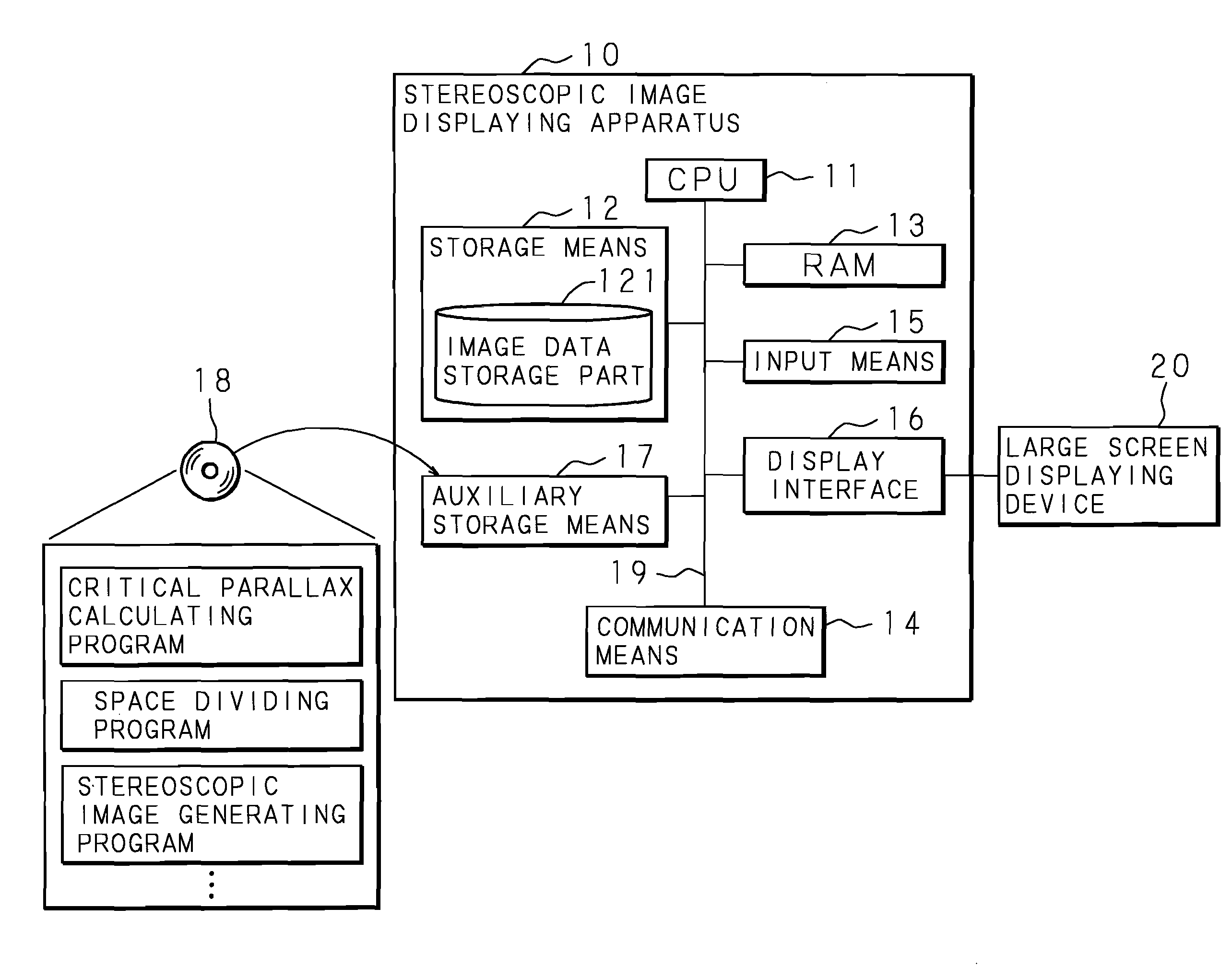
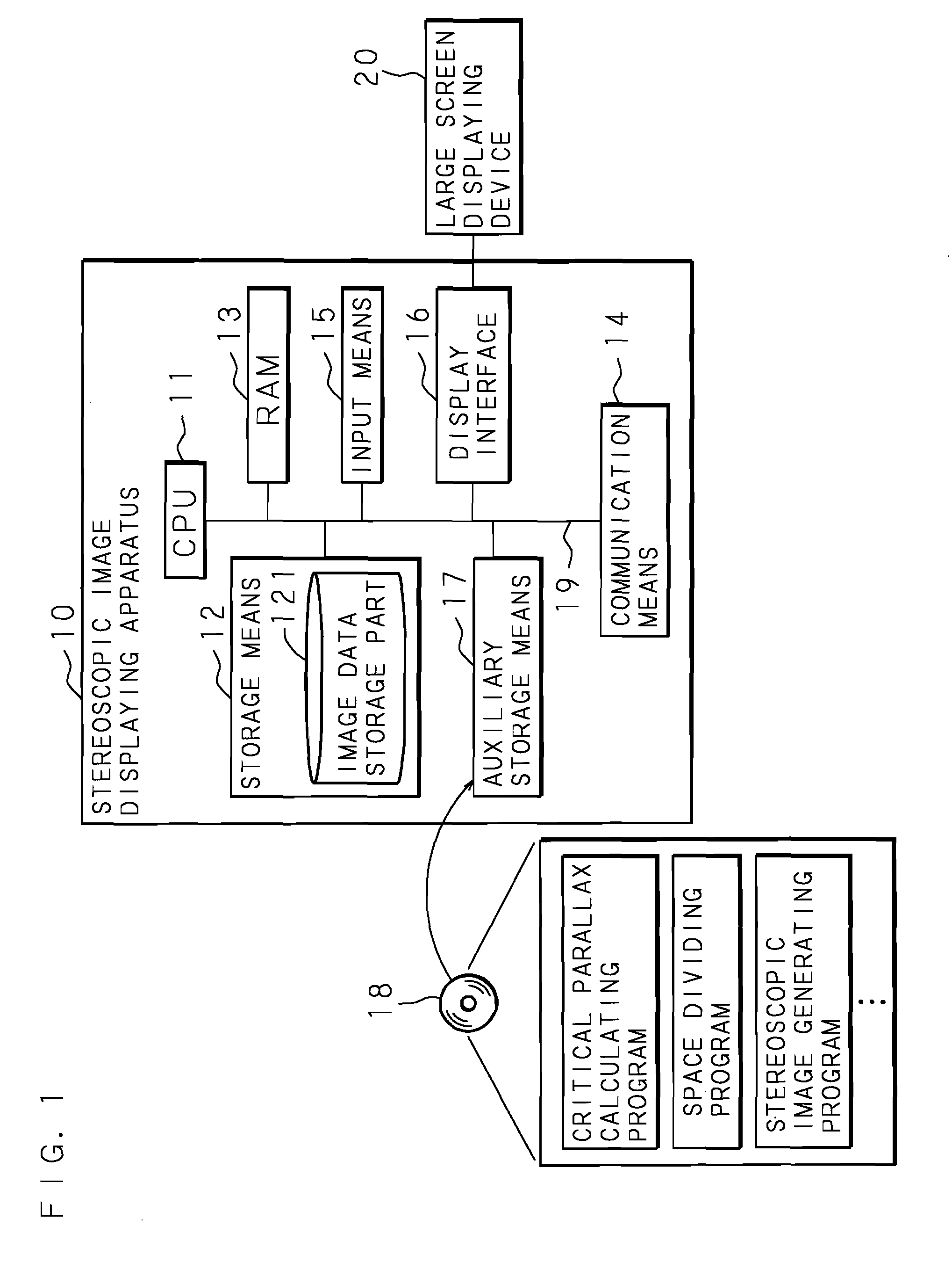
[0104]A stereoscopic image display apparatus according to Embodiment 1 of the present invention will be described below specifically on the basis of the drawings. FIG. 1 is a block diagram showing the configuration of the stereoscopic image display apparatus 10 according to Embodiment 1 of the present invention.

[0105]As shown in FIG. 1, the stereoscopic image display apparatus 10 comprises at least a CPU (central processing unit) 11, storage means 12, a RAM 13, communication means 14 for communicating with an external network, such as Internet, input means 15, a display interface 16 for outputting display image data to an external large screen display unit 20 that can be viewed by multiple viewers, and auxiliary storage means 17 that use portable recording media 18, such as DVDs and CDs.

[0106]The CPU 11 is connected to the above-mentioned hardware devices of the stereoscopic image display apparatus 10 via an internal bus 19, controls the above-mentioned hardware devices, and execute...

embodiment 2

[0148]A stereoscopic image display apparatus according to Embodiment 2 of the present invention will be described below specifically on the basis of the drawings. FIG. 14 is a block diagram showing the configuration of the stereoscopic image display apparatus 10 according to Embodiment 2 of the present invention. As shown in FIG. 14, since the configuration of the stereoscopic image display apparatus 10 according to Embodiment 2 of the present invention is similar to that according to Embodiment 1, similar components are designated by the same numerals, and their detailed descriptions are omitted. Embodiment 2 is characterized in that a stereoscopic image is transmitted to an external display unit 30 that can be seen by a single viewer instead of the large screen display unit 20 that can be seen by numerous viewers, and that the critical parallax being used as the reference for generating the stereoscopic image is corrected on the basis of the distance to the screen from the viewer ...


PUM


Abstract

A stereoscopic image display apparatus which can accurately visually recognize all the regions of a stereoscopic image without using a varifocal lens, and can form a natural three-dimensional image on a retina with a processing load on a computer eased even if an image is viewed by a plurality of viewers from any positions. A stereoscopic image display apparatus for generating a stereoscopic image that forms three-dimensional image on a retina of a viewer and displaying it, wherein a critical parallax that is the boundary of parallax capable of forming a three-dimensional image on a retina of a viewer is calculated, the dimensions of rectangular parallelepiped inscribing a sphere having a diameter as the calculated critical parallax are calculated, a space including an object is divided into a plurality of spaces using the calculated rectangular parallelepiped, a stereoscopic image of the object with respect to a single gazing point is generated for each divided space, and the plurality of generated stereoscopic images are pasted together to generate a single stereoscopic image and display the generated single stereoscopic image.

Description

CROSS-REFERENCE TO RELATED APPLICATIONS[0001]This application is a U.S. national phase application under 35 U.S.C. §371 of International Patent Application No. PCT / JP2005 / 022762, filed on Dec. 12, 2005, and claims the benefit of Japanese Patent Application No. 2005-080482, filed on Mar. 18, 2005, both of which are incorporated by reference herein. The International Application was published in Japanese on Sep. 28, 2006 as International Publication No. WO 2006 / 100805 A1 under PCT Article 21(2).TECHNICAL FIELD[0002]The present invention relates to a stereoscopic image display apparatus, a stereoscopic image displaying method and a computer program product for generating and displaying a stereoscopic image, capable of forming a three-dimensional image on a retina regardless of the viewing position of a viewer and capable of allowing the viewer to naturally grasp the spatial positional relationship of an object by using the parallax between the eyes of the viewer.BACKGROUND ART[0003]Wit...

Claims


Application Information

Patent Timeline
Patent Type & Authority Applications(United States)
IPC IPC(8): H04N13/00
CPCH04N13/0003H04N13/0278H04N13/0014H04N13/10H04N13/117H04N13/279
Inventor HIRAMATSU, KOICHIUCHIMURA, TAKAOSUUCHI, YASUHITOOKADA, TADANORIHATTORI, KAZUYUKITAKEUCHI, SYUNSAKU
Owner NTT DATA SANYO SYST
Why Eureka
Try Eureka