
Digital TV receiver with a built-in antenna

Inactive Publication Date: 2008-08-14
ANHUI HAIHUA CHEM
View PDF3 Cites 25 Cited by
  • Summary
  • Abstract
  • Description
  • Claims
  • Application Information

AI Technical Summary

Benefits of technology

[0007]One particular aspect of the present invention is to provide a digital TV receiver with a built-in antenna. The digital TV receiver makes an antenna disposed inside a rotation element. The rotation element can be received by rotating or moving the rotation element. In other words, because the antenna is disposed inside the rotation element, it is easy for user to receive the antenna by control the rotation element.
[0010]Therefore, it is easy for user to use and receive the antenna of the digital TV receiver due to the design of the rotation element.

Problems solved by technology

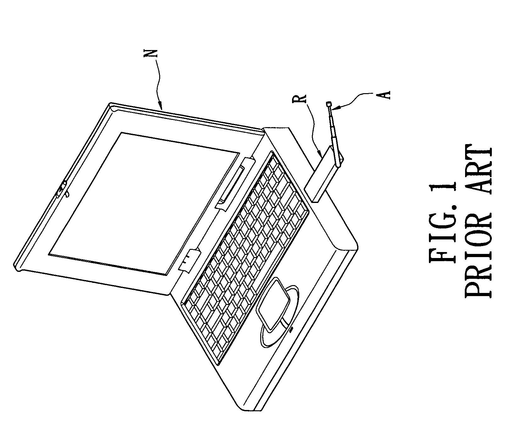
However, the antenna A of the prior art is exposed outside the digital TV receiver R, so that it is difficult and inconvenient for user to receive the antenna A and carry the digital TV receiver R.

Method used


Image

  • Digital TV receiver with a built-in antenna
  • Digital TV receiver with a built-in antenna
  • Digital TV receiver with a built-in antenna

Examples


first embodiment

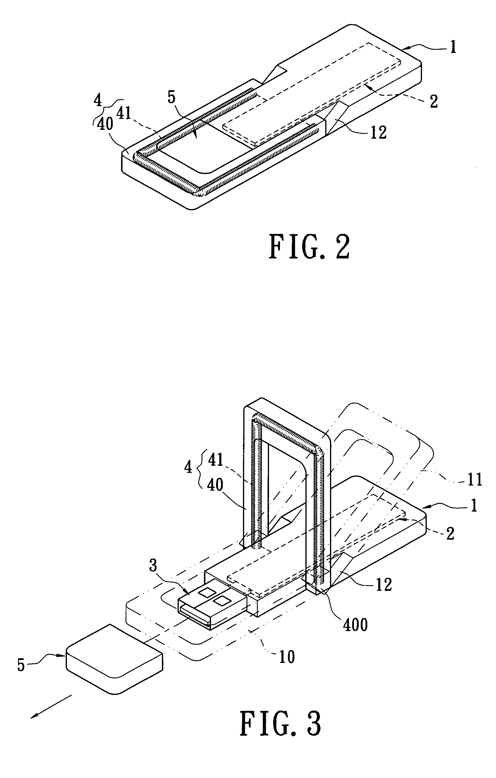
[0021]Referring to FIGS. 2 to 4, the present invention provides a digital TV receiver with a built-in antenna that includes a casing unit 1, a circuit unit 2, an output unit 3, an antenna unit 4 and a protection cover 5.

[0022]The circuit unit 2 is disposed inside the casing unit 1. The output unit 3 is electrically connected to the circuit unit 2. The output unit 3 is disposed on one side of the casing unit 1 and is exposed outside the casing unit 1. Hence, the digital TV receiver can electrically connect to a computer system (not shown) via the output unit 3 in order to transmitting digital TV signals. In the first embodiment, the output unit 3 can be a USB connector. In other embodiment, the output unit 3 can be other interface connector such as IEEE1394 interface, RS232 interface or Mini USB interface.

[0023]Moreover, the antenna unit 4 has a rotation element 40 pivoting around the casing unit 1 and an antenna 41 disposed inside the rotation element 40, and the antenna unit 4 is e...

second embodiment

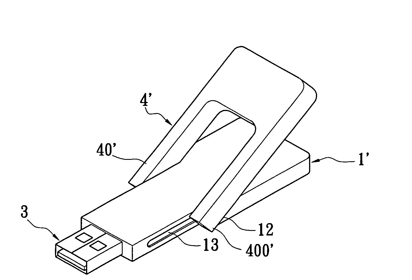
[0026]Referring to FIGS. 5 to 8, the present invention provides a digital TV receiver with a built-in antenna that includes a casing unit 1′, a circuit unit 2, an output unit 3, an antenna unit 4′ and a receiving space 5′.

[0027]The difference between the second embodiment and the first embodiment is that: the casing unit 1′ has two sliding slots 13 respectively formed on two sides thereof, and the rotation element 40′ of the antenna unit 4′ has two sliding sides 400′ respectively disposed on the same end sides and slidably receiving in the two sliding slots 13. In addition, the receiving space 5′ of the rotation element 40′ is formed on another opposite end side for mating with the casing unit 1′ and receiving the output unit 3. Hence, the first position is a covering position 10′ for making the output unit 3 received in the receiving space 5′ of the rotation element 40′, and the rotation element 40′ is selectively positioned at the covering position 10′. The second position of the ...


PUM


Abstract

A digital TV receiver with a built-in antenna includes a casing unit, a circuit unit, an output unit, an antenna unit and a protection cover. The circuit unit is disposed inside the casing unit. The output unit is electrically connected to the circuit unit and exposed outside the casing unit. The antenna unit has a rotation element pivoting around the casing unit and an antenna disposed inside the rotation element and electrically connected to the circuit unit. The rotation element is rotatably positioned at a first position close to the output unit and a second position far away from the output unit. The protection cover mates with the casing unit for covering the output unit. The first position is a retaining position for making the protection cover retained on the casing unit. The second position is an inclined position for making the rotation element inclined relative to the casing unit.

Description

BACKGROUND OF THE INVENTION[0001]1. Field of the Invention[0002]The present invention relates to a digital TV receiver, and particularly relates to a digital TV receiver with a built-in antenna.[0003]2. Description of the Related Art[0004]Digital TV is a new wireless TV technology, and its texts and images are digital, that is coded in zeros and ones, the same as in computers. Hence, the user can store and adjust frame and information that user wants. Noise is reduced and the sound and picture quality is better (similar to DVD) due to digital wireless transmission. Originally one TV station can provide one channel; now one TV station can provide three or four different channels due to the image compression technology.[0005]Referring to FIG. 1, when a digital TV receiver R of the prior art is inserted into a notebook N, the digital TV receiver R has an antenna A for receiving digital TV signals. In addition, the digital TV signals need to be decoded via the digital TV receiver R in o...

Claims


Application Information

Patent Timeline
IPC IPC(8): H04N5/44
CPCH04N5/64H04N5/44
Inventor LEE, TSENG-CHIEH
Owner ANHUI HAIHUA CHEM
Learn More