Radar antenna and radar antenna manufacturing method

Active Publication Date: 2014-05-29
FURUNO ELECTRIC CO LTD
View PDF3 Cites 5 Cited by
  • Summary
  • Abstract
  • Description
  • Claims
  • Application Information

AI Technical Summary

Benefits of technology

[0013]Thus, the antenna unit can be separated from the housing unit with the simple configuration. Although influence of wind is easily received due to the separation of the antenna unit from the housing unit, wind can pass through between the plurality of supporting bars with the configuration described above. Therefore, the radar antenna can be support

Problems solved by technology

However, with the antenna unit having the dielectric bodies as disclosed in JP1991-042723

Method used


Image

  • Radar antenna and radar antenna manufacturing method
  • Radar antenna and radar antenna manufacturing method
  • Radar antenna and radar antenna manufacturing method

Examples


Example

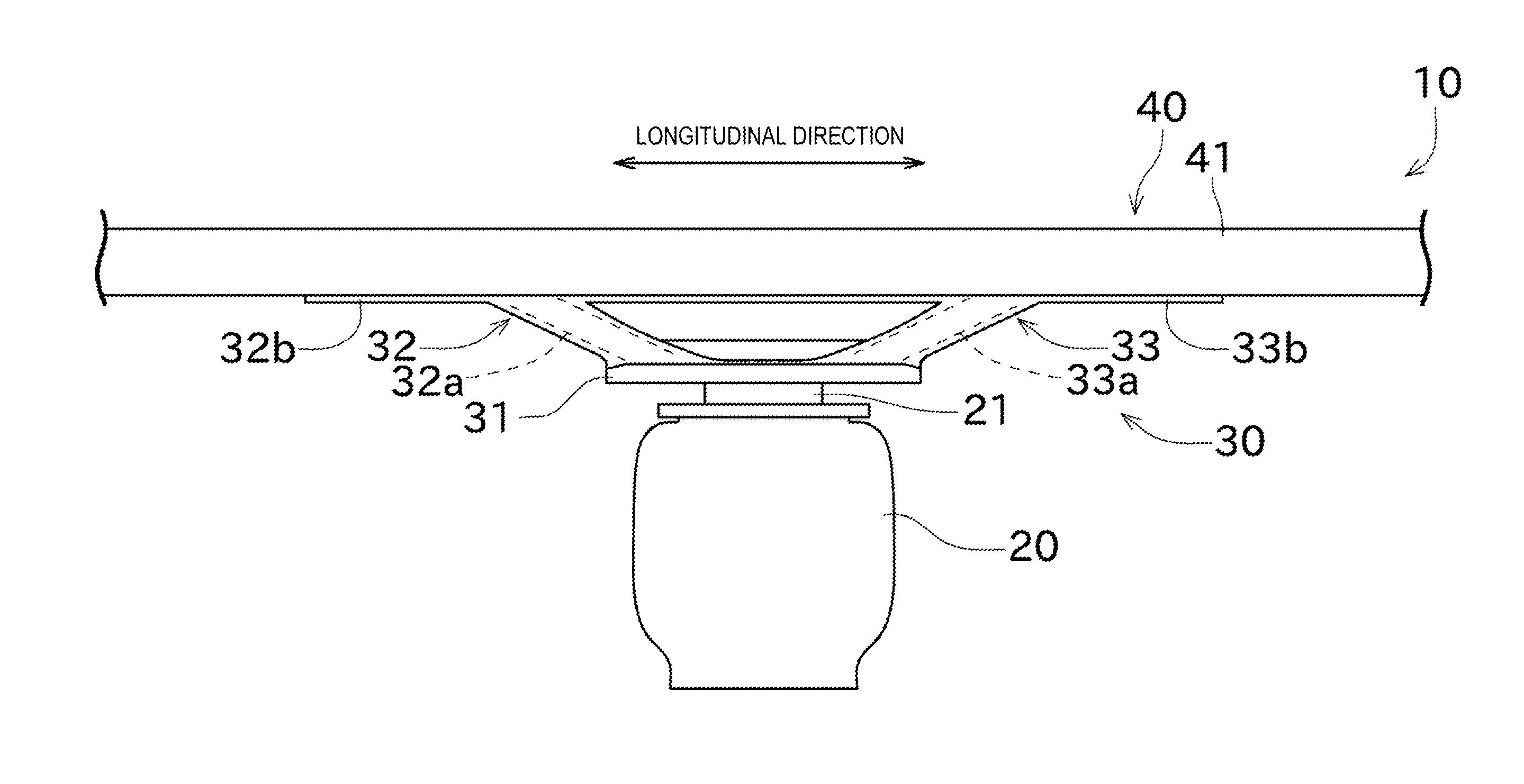
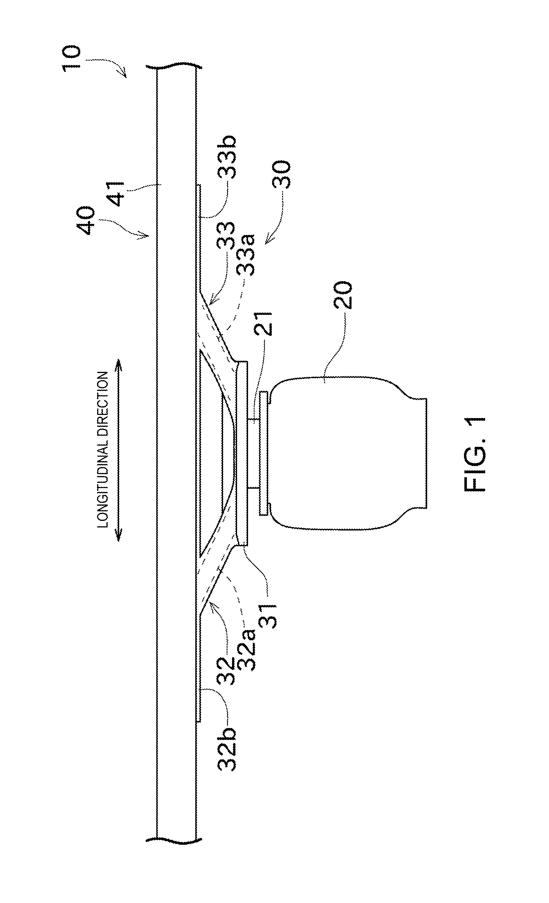
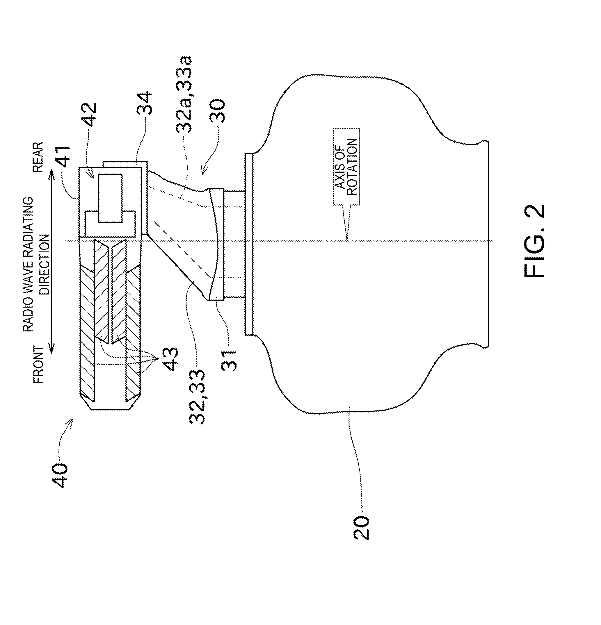
[0038]Next, one embodiment of the present invention is described with reference to the accompanying drawings. FIG. 1 is a schematic front view of a radar antenna according to this embodiment of the present invention. FIG. 2 is a schematic side view of the radar antenna.

[0039]A radar antenna 10 radiates pulse-shaped radio waves and receives reflection waves of the radiated radio waves. The radar antenna 10 repeats transception of the radio waves while rotating in the horizontal plane. Each reflection wave received by the radar antenna 10 is analyzed by a transceiver, an indicator and the like (not illustrated). Thus, a position, a speed and the like of a target object existing around the radar antenna 10 can be obtained.

[0040]As illustrated in FIGS. 1 and 2, the radar antenna 10 includes a housing unit 20, an antenna supporting unit 30, and an antenna unit 40 having dielectric bodies.

[0041]The housing unit 20 is a box-like member accommodating various components. The housing unit 20 ...


PUM

PropertyMeasurementUnit
Shapeaaaaaaaaaa

Abstract

A radar antenna is provided. The radar antenna includes an antenna unit provided with dielectric bodies in a front part thereof in a radio wave radiating direction, a housing unit for supplying a radio wave to the antenna unit, and an antenna supporting unit made of FRP attached between the antenna unit and the housing unit to separate the antenna unit from the housing unit.

Description

CROSS-REFERENCE TO RELATED APPLICATION(S)[0001]This application claims priority under 35 U.S.C. §119 to Japanese Patent Application No. 2012-258700, which was filed on Nov. 27, 2012, the entire disclosure of which is hereby incorporated by reference.TECHNICAL FIELD[0002]The present invention relates to a radar antenna including an antenna unit having dielectric bodies.BACKGROUND OF THE INVENTION[0003]Conventionally, radar antennas each including an antenna unit and a housing unit has been known. The antenna unit radiates outside radio waves. The housing unit is built therein with a motor for rotating the antenna unit, a coaxial cable for supplying radio waves to the antenna unit, etc.[0004]Moreover, various kinds of antenna units have conventionally been known, such as, an antenna unit having a shape in which the cross-section of an opening part thereof gradually spreads toward outside (horn shape, trumpet shape). In supporting the horn-shaped antenna unit, it has been known that ev...

Claims


Application Information

Patent Timeline
IPC IPC(8): H01Q1/22
CPCH01Q3/04H01Q13/24H01Q1/1207Y10T29/49016H01Q1/22H01Q13/28
Inventor ATSUMI, KOJIODA, MAKOTO
Owner FURUNO ELECTRIC CO LTD
Why Eureka
Try Eureka