Lubrication structure in engine

Active Publication Date: 2005-06-30
SUBARU CORP
View PDF3 Cites 5 Cited by
  • Summary
  • Abstract
  • Description
  • Claims
  • Application Information

AI Technical Summary

Benefits of technology

[0012] It is another object of the present invention to provide a lubrication structure wherein the oil groove is supplied with increased amount of oil by easily receiving oil splash in the crank case, wherein the oil groove has a tapered surface which increases in diameter from the first end of the oil groove to the second end of the oil groove.
[0013] It is still another object of the invention to provide a lubrication structure wherein the perforating operation is easily carried out a

Problems solved by technology

According to the structure shown in FIG. 8, however, it is possible that sufficient lubrication is not provided.
Therefore, it is difficult to provide a space with a si

Method used


Image

  • Lubrication structure in engine
  • Lubrication structure in engine
  • Lubrication structure in engine

Examples


Example

[0027] Other features of this invention will become apparent in the course of the following description of exemplary embodiments, which are given for illustration of the invention and are not intended to be limiting thereof.

[0028] A lubrication structure of a connecting rod big-end in the engine according to the present invention will now be explained by referring to the figures. In the figures, the same reference denotes the same members.

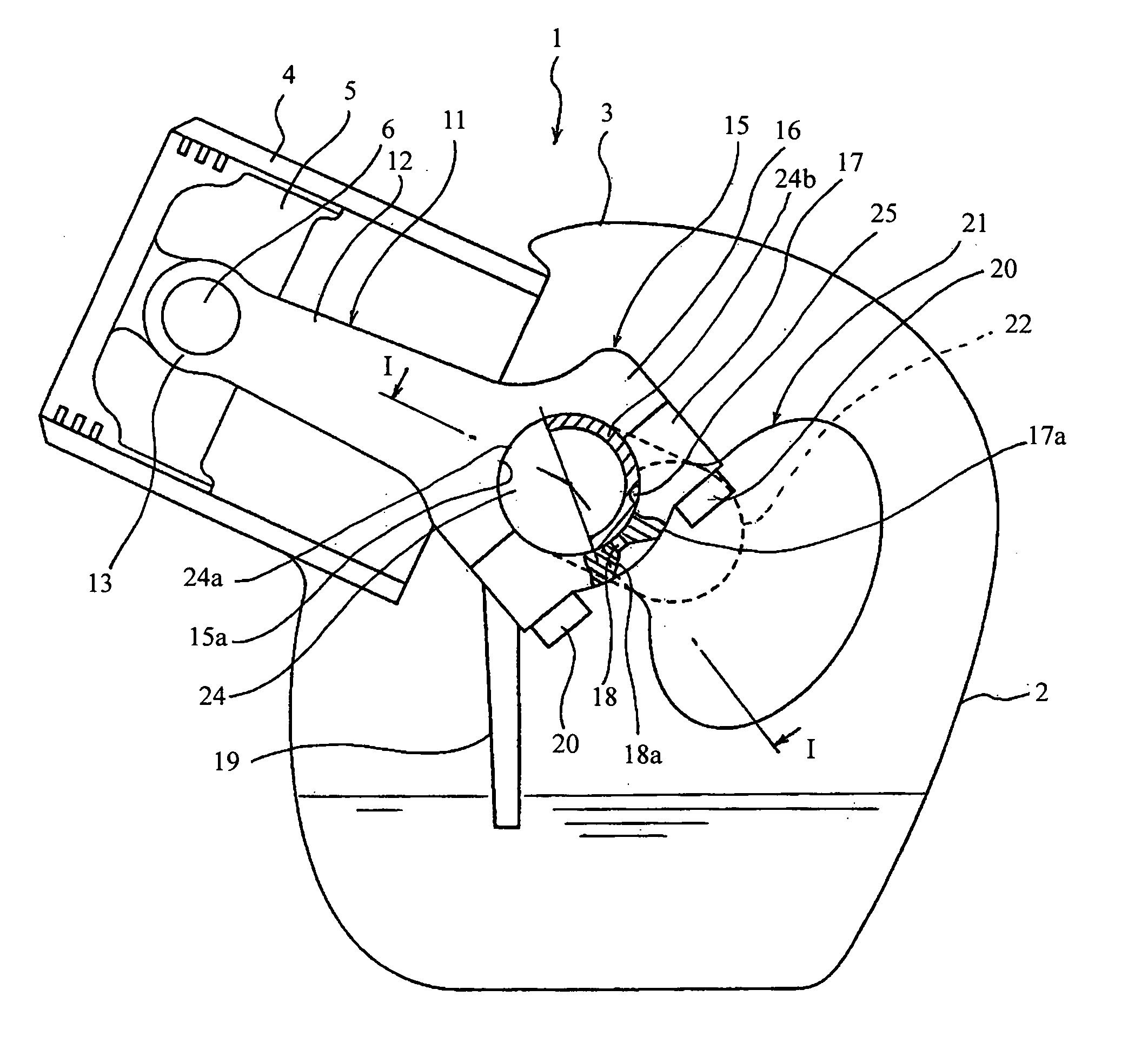
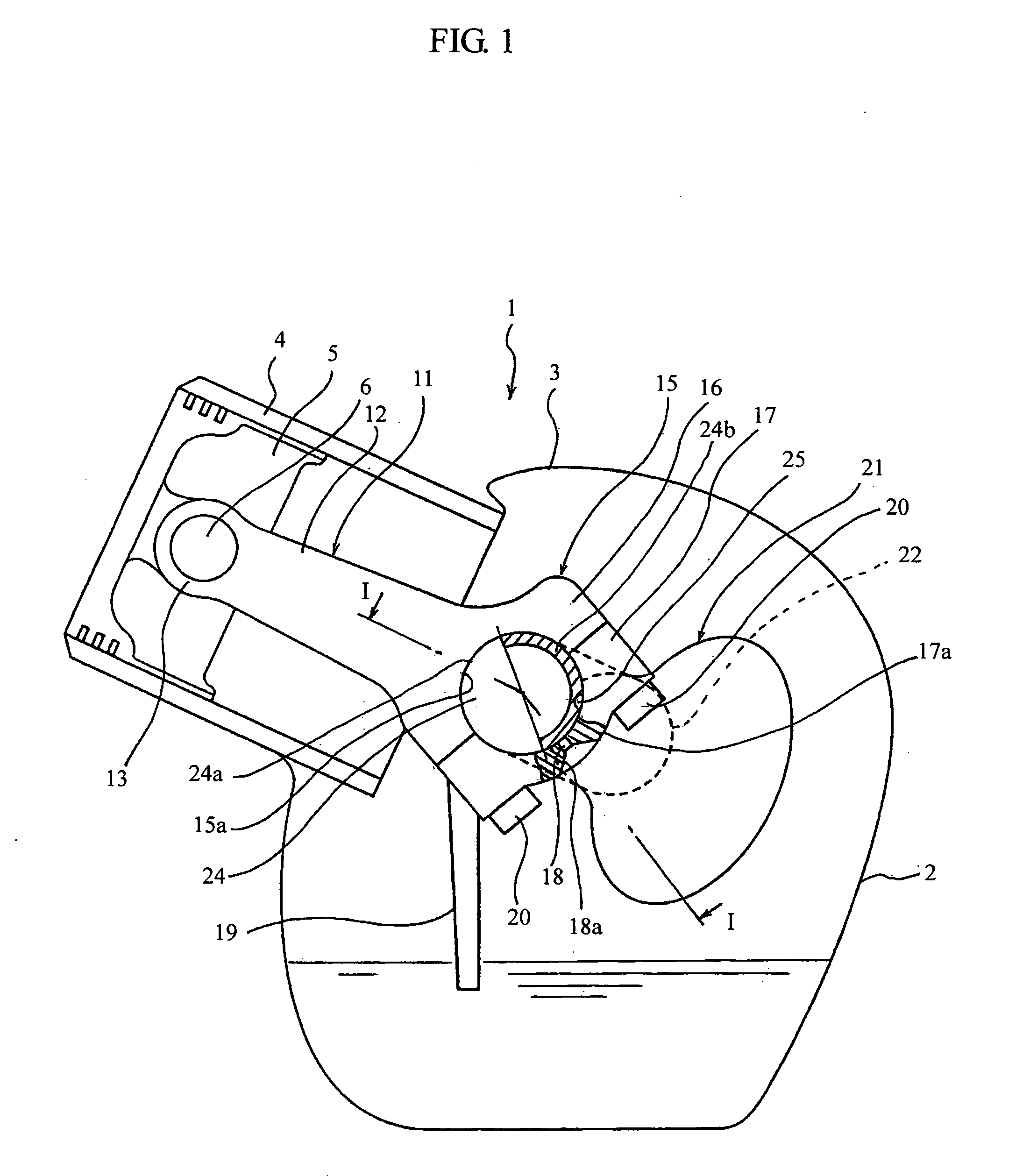
[0029]FIG. 1 is a front view for schematically showing an engine having a lubrication structure according to the present invention, and FIG. 2 is a cross-section of FIG. 1 cut along a line I-I.

[0030] An engine 1 is a splash lubrication-type 4-cycle engine. The engine 1 is structured from a crank case 2 and a cylinder case 3 connected thereto. The cylinder case 3 includes a cylinder portion 4 having a cylinder bore therein. A cylinder head (not shown) is attached to the top of the cylinder portion 4.

[0031] A piston 5 is provided in the cylinder ...


PUM


Abstract

A lubrication structure for splash lubrication in an engine includes an oil collector formed as a depression in the outer peripheral surface of the crank pin and an oil groove provided on the big-end of the connecting rod. The oil collector is formed approximately at the center, in an axial direction, of the crank pin. The position of the oil collector is chosen so as to be displaced from an explosive force in an expansion cycle of the engine. The oil groove is provided on the big-end of the connecting rod, and has a first end and a second end. The first end is open in the inner peripheral surface at the center thereof in an axial direction, and the second end is open into the crank case. The oil collector receives oil stored in the crank case and the oil is transferred to the oil groove.

Description

BACKGROUND OF THE INVENTION [0001] 1. Field of the Invention [0002] The present invention relates to a lubrication structure in an engine, and more specifically, to a lubrication structure of a connecting rod big-end in a splash lubrication engine. [0003] 2. Discussion of the Related Art [0004] In an engine, a piston contained in a cylinder is connected to a crank shaft via a connecting rod. The connecting rod has a small-end connected to the piston so as to allow the piston to make a reciprocating movement in a bore of the cylinder part. The connecting rod has a big-end connected to a crank pin in a crank case, so as to rotate with respect to each other. [0005]FIG. 8 is a diagram for explaining a known method for lubricating a connecting rod big-end and a crank pin, as described in Japanese Kokai Publication 1996-284944. In FIG. 8, a ring-shaped big-end 102 of a connecting rod 101 is divided into a big-end first half 103 and a big-end second half 104 along a diameter line of an inn...

Claims


Application Information

Patent Timeline
IPC IPC(8): F01M9/06F16C9/04F02M9/06
CPCF01M9/06
Inventor FURUYA, AKIRA
Owner SUBARU CORP
Why Eureka
Try Eureka