Engine oil system with oil pressure regulator to increase cam phaser oil pressure

Inactive Publication Date: 2005-03-24
GENERAL MOTORS CORP
View PDF0 Cites 33 Cited by
  • Summary
  • Abstract
  • Description
  • Claims
  • Application Information

AI Technical Summary

Benefits of technology

[0010] The restriction of oil flow to the main gallery created by the regulator forms back pressure which increases oil pressure in the main feed. The increased oil pressure within the main feed is then directed to the hydraulically actuated device. As a result, the amount of oil pressure to the hydraulically actuated device is increased while the rest of the oil system operates at a lower oil pressure. This allows cam phasing

Problems solved by technology

However, smaller oil pumps do not provide enough oil pressure to actuate a cam phaser at low and idle engine speeds.
However, the efficiency gains are not without cost.
A higher pressure produced by

Method used


Image

  • Engine oil system with oil pressure regulator to increase cam phaser oil pressure
  • Engine oil system with oil pressure regulator to increase cam phaser oil pressure
  • Engine oil system with oil pressure regulator to increase cam phaser oil pressure

Examples


Example

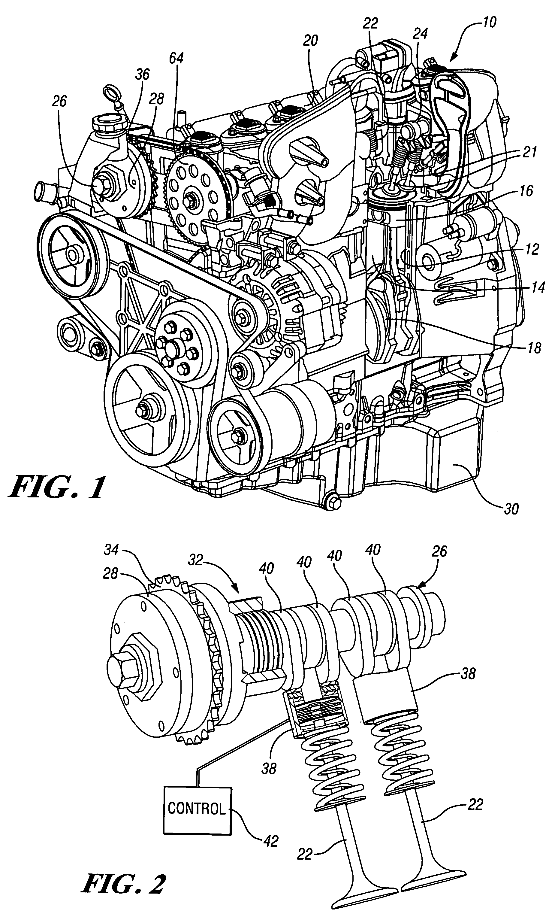
[0016] Referring now to FIG. 1 of the drawings in detail, numeral 10 generally indicates an internal combustion engine. The engine includes a cylinder block 12 having a bank of cylinders 14 containing pistons 16 connected with a crankshaft 18. A cylinder head 20 carries intake and exhaust valves 21, 22 actuated by camshafts 24, 26. A cam phaser 28 is mounted on the exhaust camshaft 26 to vary the exhaust valve timing. An oil pan 30 below the block forms an oil sump for the engine.

[0017]FIG. 2 illustrates an exhaust portion of an engine valve train 32 for use in an overhead cam piston type engine. The valve train 32 includes exhaust camshaft 26 which is driven through a drive sprocket 34 connected by a chain 36 with the engine crankshaft 18. Cam phaser 28 is connected between the sprocket 34 and the camshaft 26 in order to vary the timing of the camshaft relative to the piston motion and other operating functions of the engine and relative to other camshafts of the engine.

[0018] Th...


PUM


Abstract

A lubrication system for an internal combustion engine having a pressure regulator to optimize oil flow through an engine to increase engine efficiency. The lubrication system includes an engine driven oil pump connected to supply pressurized oil through a main oil feed to a main bearing gallery, a cam gallery and a hydraulically actuated device such as a cam phaser or switching valve lifters. A pressure regulator connected between the main oil feed and the galleries selectively restricts oil flow to the galleries to raise oil pressure supplied to the hydraulically actuated device. The increased oil pressure to the cam phaser allows the engine to use a smaller oil pump and thereby increase engine efficiency while providing for actuation of the cam phaser over the full engine speed range. The increased oil pressure to the switching lifters allows the engine to reduce valve lift or disable cylinders over the full engine speed range.

Description

TECHNICAL FIELD [0001] This invention relates to engine oil systems and, more particularly, to a system including a pressure regulator to optimize oil flow and pressure for various lubrication and actuation functions. BACKGROUND OF THE INVENTION [0002] Internal combustion engines may use lubricating oil for many purposes including, for example, lubricating moving parts, actuating cam phasers, and controlling valve lifters for cylinder deactivation. Cam phasers and cylinder deactivation devices generally require a higher oil pressure for actuation during engine operation than the moving parts of the engine require for proper lubrication. [0003] One approach to maximize engine efficiency is to use a smaller oil pump to provide only the minimum amount of oil pressure needed to prevent engine wear. However, smaller oil pumps do not provide enough oil pressure to actuate a cam phaser at low and idle engine speeds. Thus the cam phaser can be operated only at higher engine speeds. [0004] A...

Claims


Application Information

Patent Timeline
IPC IPC(8): F01L1/14F01L1/24F01L1/34F01L13/00F01M1/06F01M1/16F01M9/10F01M11/02
CPCF01L1/022F01L1/24F01L1/34F01L13/0005F01L13/0015F01M11/02F01L2001/34423F01L2001/3444F01M1/16F01M9/10F01L2001/0537
Inventor PLENZLER, JEREMY M.ZHENG, LIYUN
Owner GENERAL MOTORS CORP
Why Eureka
Try Eureka