
Sliding material composition

Inactive Publication Date: 2010-04-15
NTN CORP
View PDF2 Cites 0 Cited by
  • Summary
  • Abstract
  • Description
  • Claims
  • Application Information

AI Technical Summary

Benefits of technology

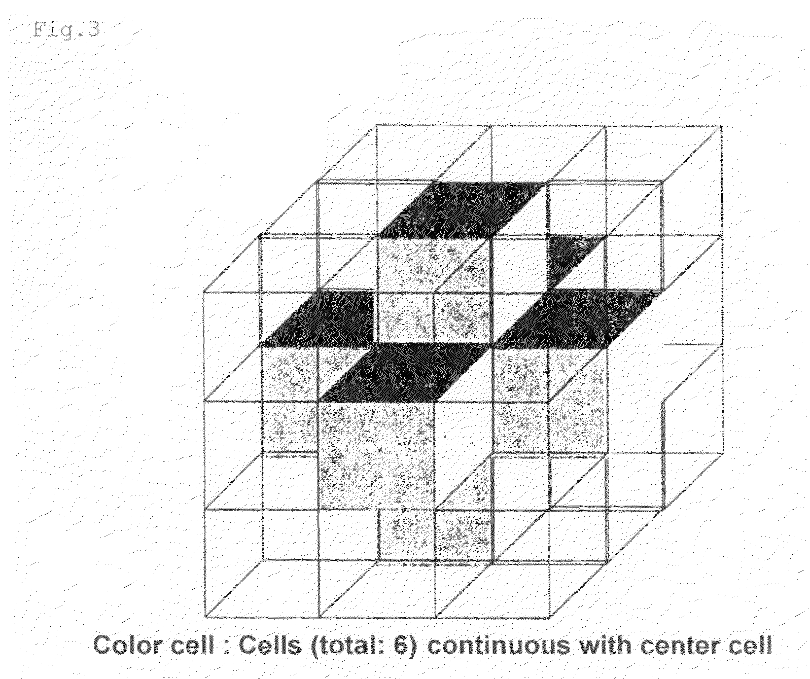
[0022]The sliding material composition comprises the resin material with which at least the porous silica and the lubricant are mixed; and the ratio of the sum of the mixing amount of the porous silica and that of the lubricant to the whole amount of the sliding material composition is 30 to 60 vol %. Therefore the lubricant is held inside the porous silica, and the lubricant can be supplied little by little to the sliding interface. Further the oil-containing porous silica in which the lubricant is held by the porous silica is connected to each other inside the composition, and the interconnected cell ratio of the oil-containing porous silica found by the predetermined computing method is not less than 20%. Therefore it is possible to continuously supply the lubricant to the sliding interface and maintain excellent friction and wear properties.
[0023]Further because the porous silica is impregnated with the lubricant, it is possible to maintain the mechanical property of the sliding material composition and increase the amount of the oil to be contained therein.
[0024]The porous silica impregnated with the lubricant (oil absorption amount: 300 to 400 ml / 100 g) is mixed with the resin material. Owing to the compatibility between the resin material and the lubricating oil, it is possible without a trouble to mix and knead combinations of components that cannot be kneaded in the conventional art. In addition, because it is also possible to add the lubricant to the resin material, it is possible to mix a large amount of the lubricant thereinto. In addition the sliding material composition of the present invention does not have disadvantages that a screw slides at the time of injection molding, that a cycle time is long because metering is unstable, that it is difficult to obtain high dimensional accuracy, and that the lubricant adheres to the surface of a die and the finish of a molded surface is unfavorable.
[0025]The porous silica to be used for the sliding material composition is spherical porous silica, having continuous pores, which is an aggregate of primary fine particles, the porous silica is destroyed by the shear force of the sliding interface. Therefore even though a mating sliding material is made of a soft material, a molding of the sliding material composition does not damage the mating sliding material.
[0026]Because the average particle diameter of the spherical porous silica is 0.5 to 100 μm, the spherical porous silica has an excellent dispersibility. Therefore when the spherical porous silica is used in combination with other reinforcing materials, it is possible to prevent the lubricant from being present at the interface between the reinforcing material and the resin and obtain a desired reinforcing effect.
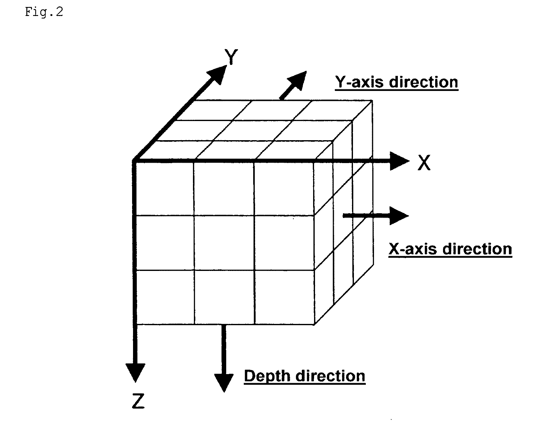
[0027]The number of cells used in the modeling step of the above-described computing method is not less than 30 cells in the X-axis direction, not less than 30 cells in the Y-axis direction, and the number of cells of one horizontal layer is set to not less than 1000. Therefore it is possible to evaluate the interconnected cell ratio of the oil-containing porous silica at a high accuracy. Consequently in the obtained sliding material composition, it is possible to accurately set the interconnected cell ratio of the oil-containing porous silica to not less than 20% and thus keep the above-described friction and wear properties.

Problems solved by technology

But when the solid lubricant is mixed with the resin material, there is a limitation in the decrease of the friction coefficient.
But when only the lubricant is mixed with the resin material and the like, there occur problems described below.
Thus it is difficult to stably produce the resin material having a constant sliding property.
But when the mixing amount of the lubricating oil is large, the sliding of a screw and a metering period of time become unstable and thus a cycle time becomes long.
Thus it is difficult to stably produce the sliding material composition.
There also occur problems that the oil sticks to a die and that it is difficult to obtain a high dimensional accuracy.
Another problem is that the lubricating oil cannot be uniformly dispersed in the resin material in dependence on the combination of the lubricating oil and the resin material, for example, a case when the compatibility between the lubricating-oil and the resin material is unfavorable.
It is difficult to control the state of the oozing of the lubricating oil.
Thus there occurs a problem that pores formed owing to the oozing of the lubricating oil causes a decrease in the strength of the resin layer.
Thus there is a possibility that a sufficient reinforcing effect cannot be obtained.
But even though the compositions of these proposals are used, there is a problem that in the recent strict friction condition (for example, high pressure), a preferable friction and wear property cannot be obtained.
This problem results from the fact that according to a mixing ratio of the porous silica and the like, a lot of porous silica not interconnected with the surface of the sliding material composition is present inside a molding and that because the lubricant held by the porous silica is not effectively utilized, the amount of the lubricant is insufficient on the surface of the sliding portion.

Method used


Image

  • Sliding material composition
  • Sliding material composition
  • Sliding material composition

Examples


example

Reference Example 1

[0084]As the porous silica, Sunsphere H33 (commercial name) produced by Asahi Glass Co. Ltd. was prepared. As the silicone oil serving as the lubricant, KF96H (commercial name) produced by Shin-Etsu Chemical Co., Ltd. was prepared. Five parts by volume of the silicone oil was sufficiently mixed with one part by volume of the porous silica to impregnate the porous silica with the silicone oil. Thereby the oil-containing porous silica (abbreviation in table 1: Si) was prepared. The obtained oil-containing porous silica was powdery and could be used as a mixing agent with the resin material.

examples 1 through 4

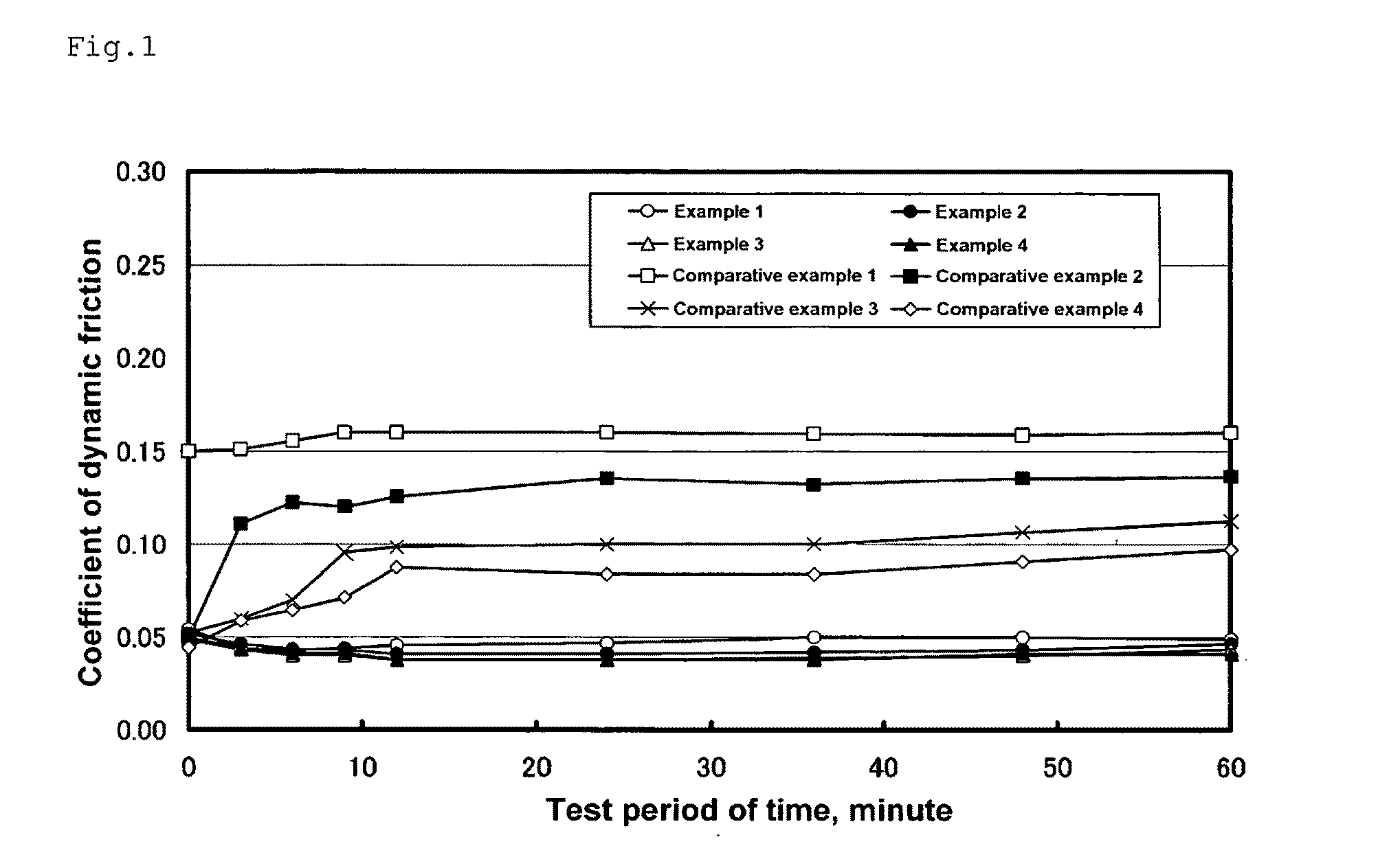
[0085]As polyethylene resin serving as the material of the base resin, Mipelon XM220 (commercial name, abbreviation in table 1: PE) produced by Mitsui Chemicals Co., Ltd. was mixed with the oil-containing porous silica prepared in the reference example 1 at the ratio shown in table 1. Mixed powder was supplied to a mold and molded by heat compression molding method. As the molding condition, temperature: 220° C., pressure: 40 MPa. Turning processing was used for each obtained molding to prepare a ring-shaped sliding material specimen which is the sliding material composition having a dimension of φ17×φ21×10 mm. By using the obtained specimen, the end face of the ring was brought into contact with a rotating disk (ring-on-disk testing machine) to conduct a friction test in conditions and an evaluation method shown below. Results are shown in FIG. 1. The abscissa axis and the ordinate axis in FIG. 1 show a test period of time (minute) and a coefficient of dynamic friction respectively...


PUM


Abstract

The present invention provides a sliding material composition that is capable of continuously supplying a lubricant to the surface of a sliding portion and has a low frictionality and a low wearability. A sliding material composition of the present invention includes a resin material with which at least porous silica and a lubricant are mixed. The ratio of the sum of the mixing amount of the porous silica and that of the lubricant to the whole amount of the sliding material composition is 30 to 60 vol %. The interconnected cell ratio of the oil-containing porous silica in which the lubricant is held by the porous silica is not less than 20% when the interconnected cell ratio is found by a predetermined computing method to be carried out by utilizing the principle of a Monte Carlo method.

Description

TECHNICAL FIELD[0001]The present invention relates to a sliding material composition capable of continuously oozing out a slight amount of a lubricant to a sliding interface.BACKGROUND ART[0002]A sliding material composition such as a resin sliding material obtained by molding a lubricous resin composition is strongly demanded to have a higher function year by year and have a low friction and a low wear in an initial state and maintain an initial sliding property thereof for a long time. Heretofore to achieve the low friction and the low wear, a resin material and other components are mixed with a solid lubricant such as graphite, polytetrafluoroethylene, molybdenum disulfide, boron nitride or the like or with a reinforcing material such as glass fiber, carbon fiber or the like to impart a sliding property to the sliding material composition. But when the solid lubricant is mixed with the resin material, there is a limitation in the decrease of the friction coefficient. To allow the...

Claims


Application Information

Patent Timeline
IPC IPC(8): C10M169/00
CPCC10M113/12C10M123/04C10M171/06C10M2201/105C10M2205/14C10M2229/02F16C33/201C10N2220/082C10N2230/06C10N2250/16C10N2250/18F16C33/043C10N2220/08C10N2020/055C10N2020/06C10N2030/06C10N2050/12C10N2050/14
Inventor EGAMI, MASAKISHIMAZU, EIICHIROU
Owner NTN CORP
Learn More