
Imaging Unit For Ophthalmological Devices, In Particular, For Fundus Cameras and Method For the Use Thereof

a technology of ophthalmological devices and imaging units, which is applied in the field of imaging units for ophthalmological devices, can solve the problems of only being able to measure the refractive power of the rear surface of the cornea, only being able to achieve the measurement of the refractive power of the cornea, and being able to achieve the measurement of the refractive power only with a great expenditure and limited accuracy, and achieving sharp restriction of the area of laser speckles

Inactive Publication Date: 2008-08-14
CARL ZEISS MEDITEC AG
View PDF8 Cites 2 Cited by
  • Summary
  • Abstract
  • Description
  • Claims
  • Application Information

AI Technical Summary

Benefits of technology

[0018]It is the primary object of the present invention to develop a solution for measuring distances and objects at the ocular fundus which enables an automatic evaluation and delivers absolute, clear measured values. The solution should be carried out if possible with an auxiliary device which is suitable, for example, for a fundus camera and can be retrofitted.
[0021]The use of an imaging unit of this kind as an accessory to ophthalmological devices also expands the possibilities for its use for absolute measurements at the ocular fundus. In addition, already existing devices can be retrofitted in this way. Although the proposed solution is suitable particularly for fundus cameras, it can also be used for other ophthalmological devices.

Problems solved by technology

While the axial length and radius of curvature of the cornea of the eye can be determined with relatively little expenditure using standardized devices, the measurement of the values of the refractive power of the rear surface of the cornea, the depth of the anterior chamber, the lens thickness, the refractive power of the lens and the ametropia, which are likewise necessary for an exact calculation, is only possible with a great expenditure and limited accuracy.
The use of multiple interference causes the formation of stripes with a high contrast and the area of laser speckle is sharply restricted.
However, it was disadvantageous in the solutions mentioned above that it was necessary to take substantial actions in the fundus camera employed.

Method used


Image

  • Imaging Unit For Ophthalmological Devices, In Particular, For Fundus Cameras and Method For the Use Thereof
  • Imaging Unit For Ophthalmological Devices, In Particular, For Fundus Cameras and Method For the Use Thereof

Examples


Embodiment Construction

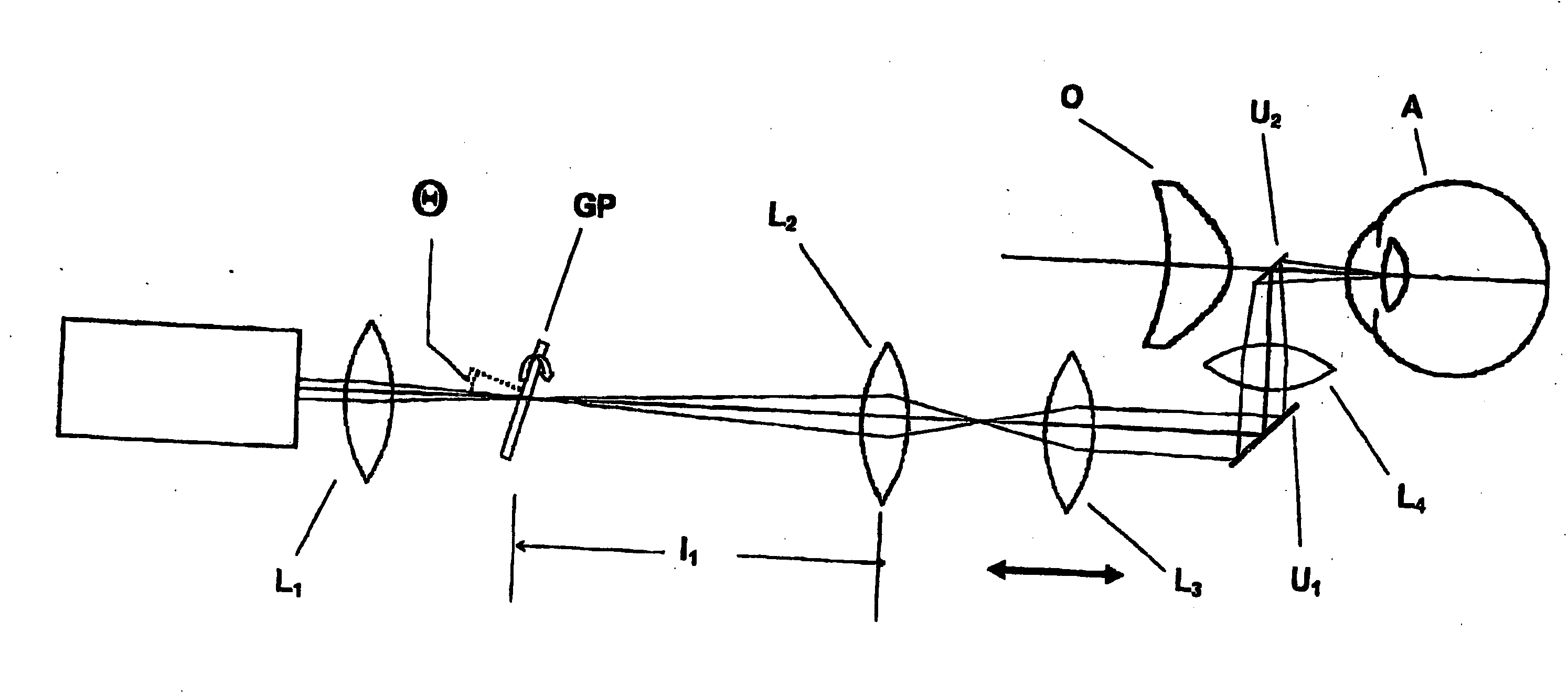
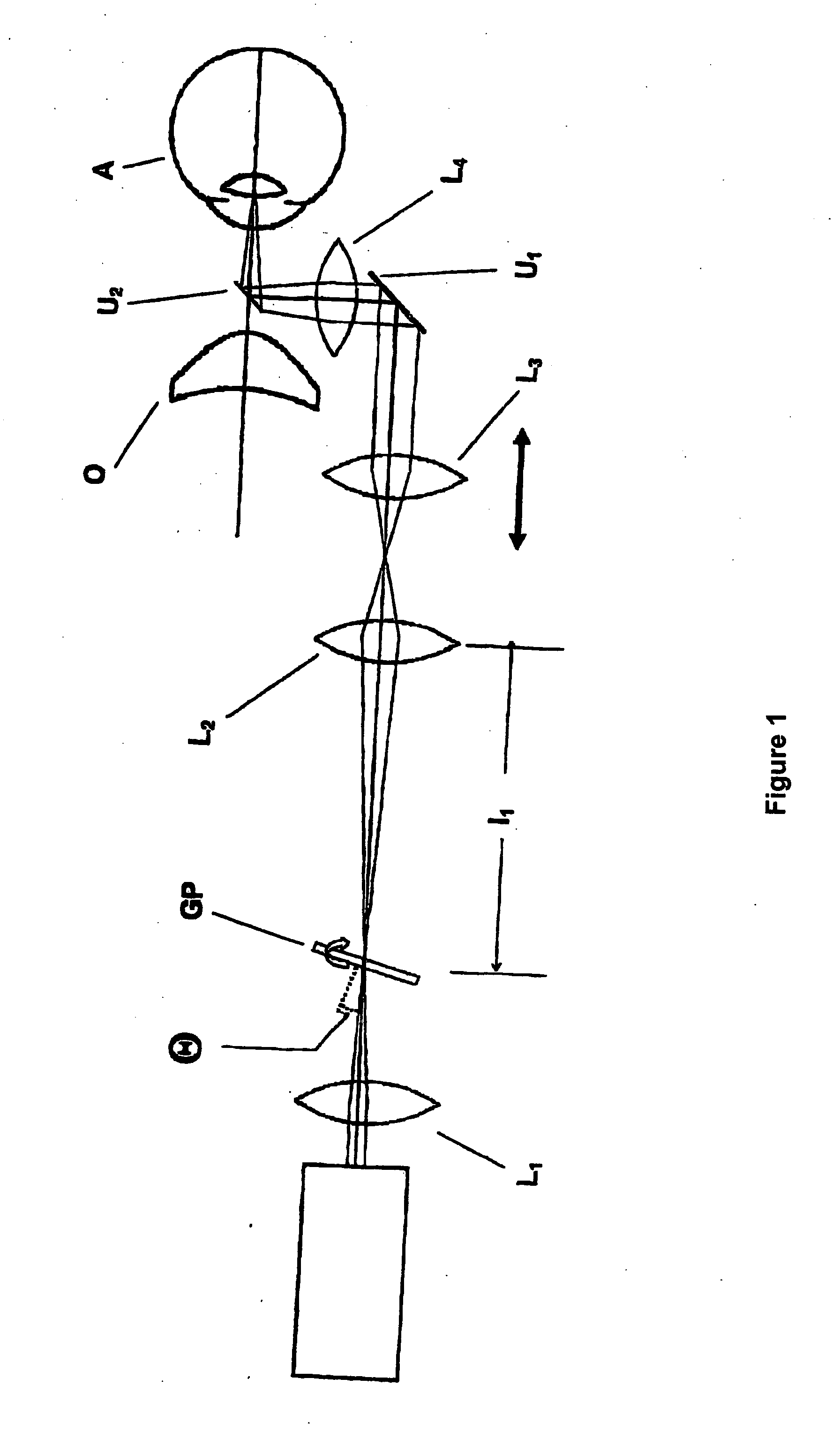
[0024]In the solution according to the invention, the imaging unit for ophthalmological devices, particularly fundus cameras, comprises a device for generating and imaging any, but a known, stripe pattern or line pattern on the retina of an eye to be examined, a camera for recording the stripe pattern or line pattern on the retina, and an evaluating unit for determining the distances on the retina. The imaging unit is constructed in such a way that the stripe pattern or line pattern to be imaged is coupled into the beam path between the ophthalmological device and the eye to be examined. For this purpose, the imaging unit is connected to the ophthalmological device, for example, a fundus camera. The stripe pattern or line pattern to be imaged can be coupled into the beam path selectively.

[0025]A multiple-beam interferometer having an arrangement for positioning the pattern at the ocular fundus is used as device for generating and imaging a stripe pattern or line pattern. The positio...


PUM


Abstract

A stripe pattern of known distance is imaged on the ocular fundus by the imaging unit for ophthalmological devices. This makes it possible to carry out absolute measurements of distances and objects at the ocular fundus with knowledge of the initial values serving as a basis. The imaging unit for ophthalmological devices, particularly fundus cameras, according to the invention comprises a device for generating and imaging any, but a known, stripe pattern or line pattern on the retina of an eye to be examined, a camera for recording the stripe pattern or line pattern on the retina, and an evaluating unit for determining the distances on the retina. The imaging unit is constructed in such a way that the stripe pattern or line pattern to be imaged is coupled into the beam path between the ophthalmological device and the eye to be examined. The use of an imaging unit of this kind as an accessory to ophthalmological devices also expands the possibilities for its use in measurements at the ocular fundus. Although the proposed solution is particularly suited to fundus cameras, it can also be used for other ophthalmological device.

Description

CROSS-REFERENCE TO RELATED APPLICATIONS[0001]This application claims priority of International Application No. PCT / EP2006 / 006002, filed Jun. 22, 2005 and German Application No. 10 2005 030 228.9, filed Jun. 29, 2005, the complete disclosures of which are hereby incorporated by reference.BACKGROUND OF THE INVENTION[0002]a) Field of the Invention[0003]The present invention is directed to an imaging unit for ophthalmological devices by which a stripe pattern of known distance is imaged on the ocular fundus. In this way, with knowledge of the initial values serving as basis, it is possible to carry out absolute measurements of distances and objects at the fundus.[0004]b) Description of the Related Art[0005]The absolute size of an object can be calculated from an image of the fundus only when all of the geometric-optical data of the camera and particularly of the eye are known. While the axial length and radius of curvature of the cornea of the eye can be determined with relatively littl...

Claims


Application Information

Patent Timeline
IPC IPC(8): A61B3/15A61B3/14
CPCA61B3/1005A61B3/185A61B3/12
Inventor BIERNAT, DETLEFKOSCHMIEDER, INGORASSOW, BERNHARDMOHR, THOMAS
Owner CARL ZEISS MEDITEC AG
Learn More