Image sensing apparatus and image sensing method

a technology of image sensing apparatus and image sensing method, which is applied in the direction of exposure control, instruments, television systems, etc., can solve the problems of not being able to calculate the flash illumination amount that would give the face the correct luminance, and not being able to control the flash illumination amoun

Inactive Publication Date: 2008-08-14
CANON KK
View PDF15 Cites 43 Cited by
  • Summary
  • Abstract
  • Description
  • Claims
  • Application Information

AI Technical Summary

Benefits of technology

[0010]The present invention has been made in consideration of the above situation, and an aspect thereof, is to control a flash illumination amount so that a face luminance is correct under a variety of different conditions.

Problems solved by technology

However, with the methods disclosed in JP-2003-107555-A and JP-2004-184508-A, there are cases where it is not possible to control the flash illumination amount so that the luminance of the face is proper when conducting flash image sensing.
Consequently, the flash illumination amount that would give the face the correct luminance cannot be calculated, and as a result, the face in a third image IM3P obtained when the flash is fired in a main flash is too dark.
The same problem arises whenever the subject moves.

Method used


Image

  • Image sensing apparatus and image sensing method
  • Image sensing apparatus and image sensing method
  • Image sensing apparatus and image sensing method

Examples


first exemplary embodiment

[0049]Next, a description is given of the operation of a first embodiment of the digital camera 100 having the configuration described above.

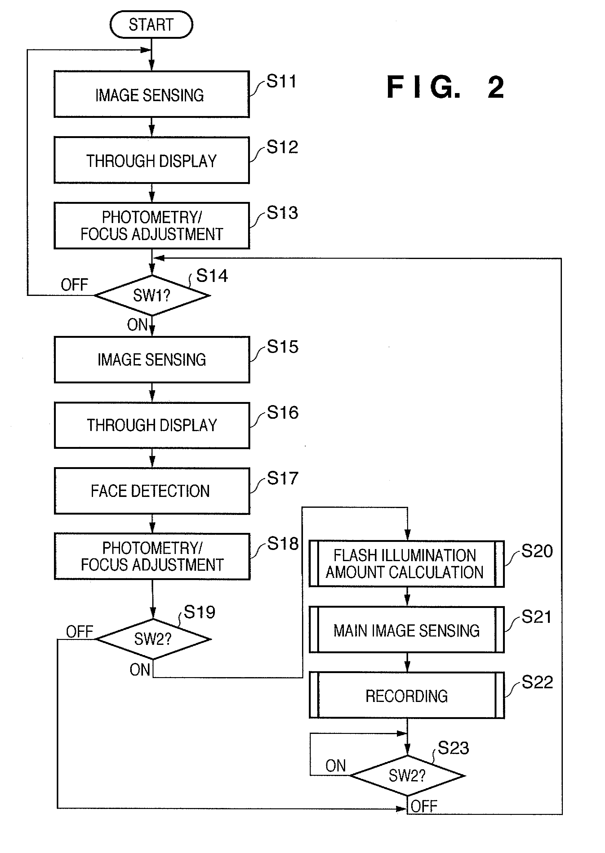
[0050]FIG. 2 is a flow chart illustrating a main routine of an image sensing mode of the digital camera 100 of the present embodiment, executed when a power switch included in the operating unit 101 is turned ON and the image sensing mode is selected.

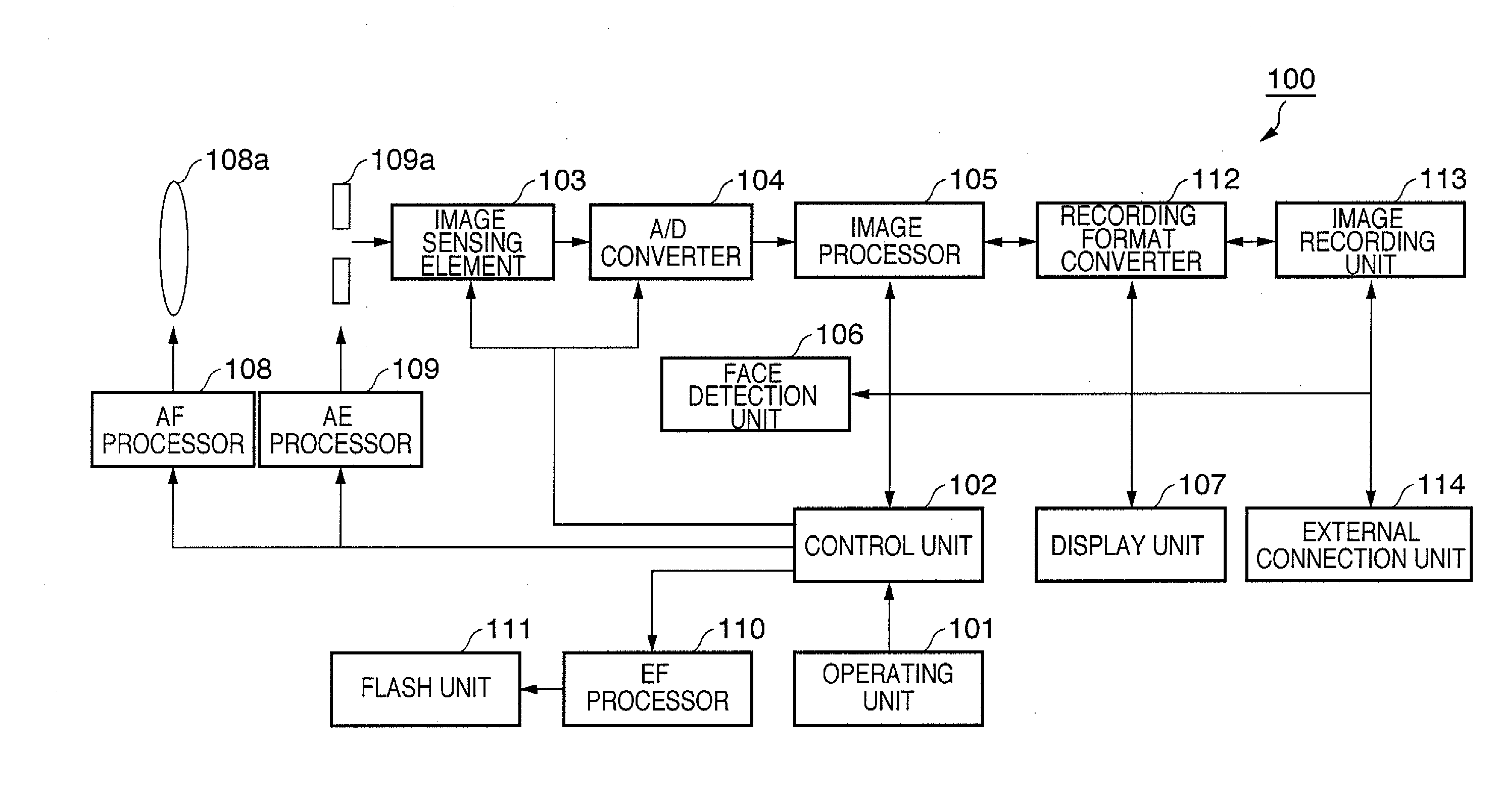
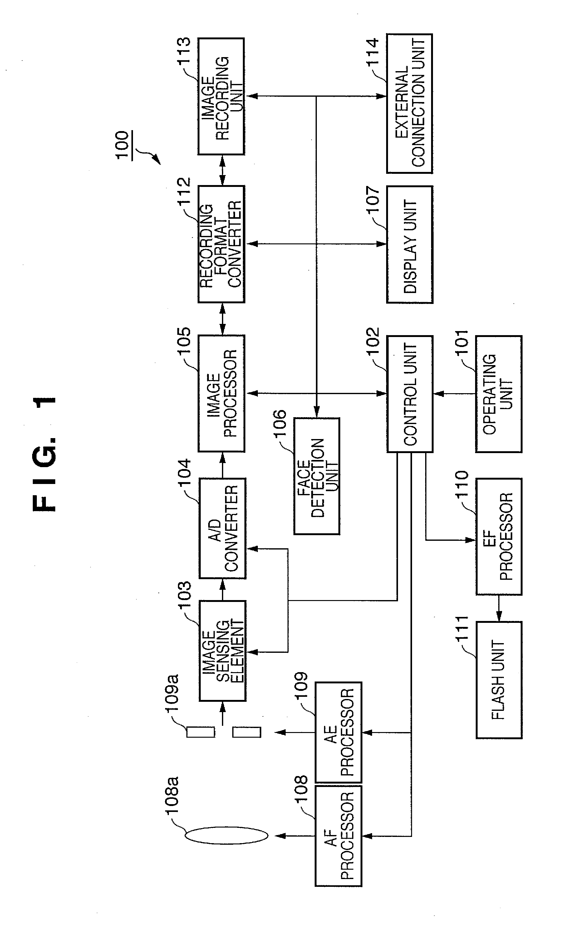
[0051]In a state in which the power switch is ON, when power is supplied to the parts that comprise the digital camera 100, the shutter included in the exposure mechanism 109a opens, allowing light to enter the image sensing element 103 through the lens 108a and the exposure mechanism 109a. In such a state, an image sensing process is carried out in step S11. Here, first, the image sensing element 103 is exposed and electrical charges accumulated for a predetermined time period by electronic shutter control are read out and output as analog image signals to the A / D converter 104. The A / D converter ...

second exemplary embodiment

[0080]Next, a description is given of a second embodiment of the present invention.

[0081]In the second embodiment, the flash illumination amount calculation process shown in FIG. 6 is carried out instead of the flash illumination amount calculation process described with reference to FIG. 3. The rest of the processing is the same as that of the first embodiment, and therefore a description thereof is omitted here.

[0082]The difference between FIG. 6 of the second embodiment and FIG. 3 described above is that, immediately after switch SW2 is turned ON, in step S203 a single image sensing operation is carried out without using the flash and the face area is detected by the face detection unit 106 from the image thus obtained. The size and position of the face area detected here is stored in a memory, not shown. An additional point of difference is that the face area is detected from the image data obtained by image sensing with the image sensing element during pre-flash.

[0083]FIG. 6 is...


PUM


Abstract

An image sensing method and image sensing apparatus, including a subject detection unit and a flash unit, are provided. The method includes a first detection step of detecting a subject from image data obtained during preparation for main image sensing, a second detection step of detecting a subject based on reflected light data obtained during pre-flash after an instruction to begin main image sensing, a step of setting a flash illumination area based on a comparison result between a first proportion of the subject detected in the first detection step within a subject area in which the subject exists and a second proportion of the subject detected in the second detection step within the subject area, a step of calculating a flash illumination amount based on the set flash illumination area, and a step of controlling the flash unit during main image sensing based on the calculated flash illumination amount.

Description

BACKGROUND OF THE INVENTION[0001]1. Field of the Invention[0002]The present invention relates to an image sensing apparatus and an image sensing method, and more particularly, to an image sensing apparatus and an image sensing method capable of detecting a subject from a sensed image.[0003]2. Description of the Related Art[0004]Conventionally, in a digital camera, there is an image sensing apparatus equipped with an automatic exposure control function that determines exposure automatically based on image data obtained by image sensing. As photometric methods carried out for the purpose of such automatic exposure control, there is, for example, evaluative photometry carried out taking the entire frame into consideration, as well as multi-division photometry, in which a photometric area within the frame is divided into a plurality of blocks and photometry carried out in blocks. In addition to these methods, there is also center-weighted photometry, in which photometry is carried out w...

Claims


Application Information

Patent Timeline
Patent Type & Authority Applications(United States)
IPC IPC(8): G03B15/03G03B15/00G03B15/05H04N5/238H04N101/00
CPCG03B7/16G03B15/05H04N5/2354H04N5/23219H04N5/23212G03B2215/05H04N23/675H04N23/61H04N23/611H04N23/635H04N23/74
Inventor MIYAZAKI, YASUYOSHI
Owner CANON KK
Why Eureka
Try Eureka