Rotary compressor

a compressor and rotary technology, applied in the direction of rotary/oscillating piston pump components, machines/engines, liquid fuel engines, etc., can solve the problems of deterioration in compressor efficiency, unintentional introduction of liquid mixture of compressed refrigerant and oil inside the hermetic container into the second compressing chamber, and above described rotary compressor may have deterioration in compression efficiency, so as to improve the sealing effect of the compressing chamber and improve compression efficiency

Inactive Publication Date: 2008-08-14
SAMSUNG ELECTRONICS CO LTD
View PDF2 Cites 16 Cited by
  • Summary
  • Abstract
  • Description
  • Claims
  • Application Information

AI Technical Summary

Benefits of technology

[0011]It is a further aspect of the invention to provide a rotary compressor capable of improving the sea

Problems solved by technology

However, in the above described conventional rotary compressor, when the first compressing chamber performs a compressing-rotation operation and the second compressing chamber performs an idling-rotation operation, the inner pressure of the second compressing chamber is lower than the inner pressure of a hermetic container, therefore a liquid mixture of compressed refrigerant and oil inside the hermetic container may be unintentionally introduced into the second compressing chamber.
Once the liquid

Method used


Image

  • Rotary compressor
  • Rotary compressor
  • Rotary compressor

Examples


Embodiment Construction

[0029]Reference will now be made in detail to the embodiments, examples of which are illustrated in the accompanying drawings, wherein like reference numerals refer to the like elements throughout. The embodiments are described below to explain the present invention by referring to the figures.

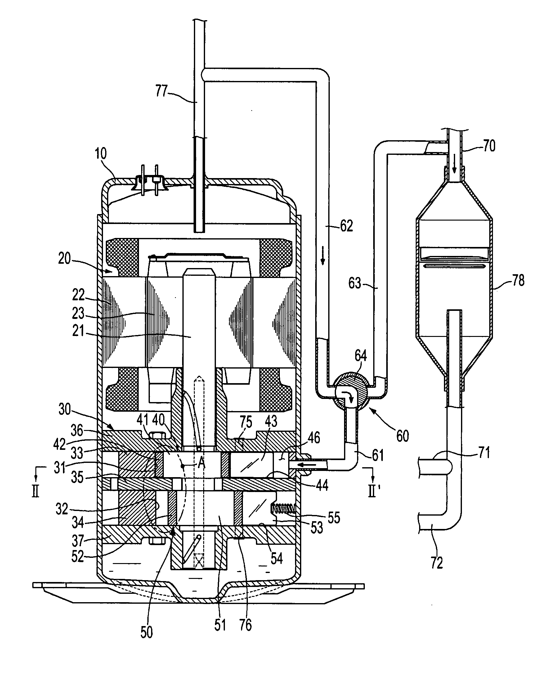
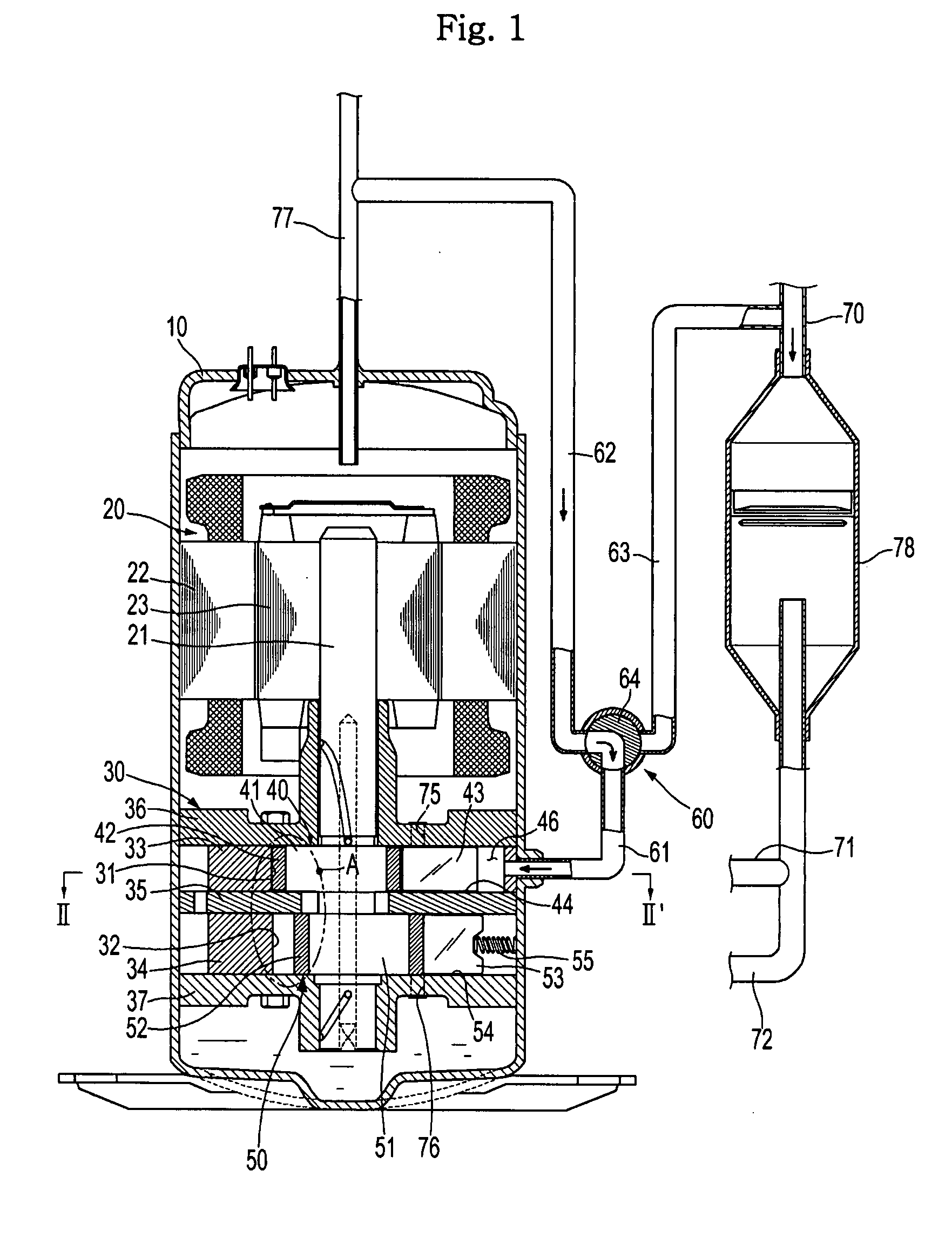
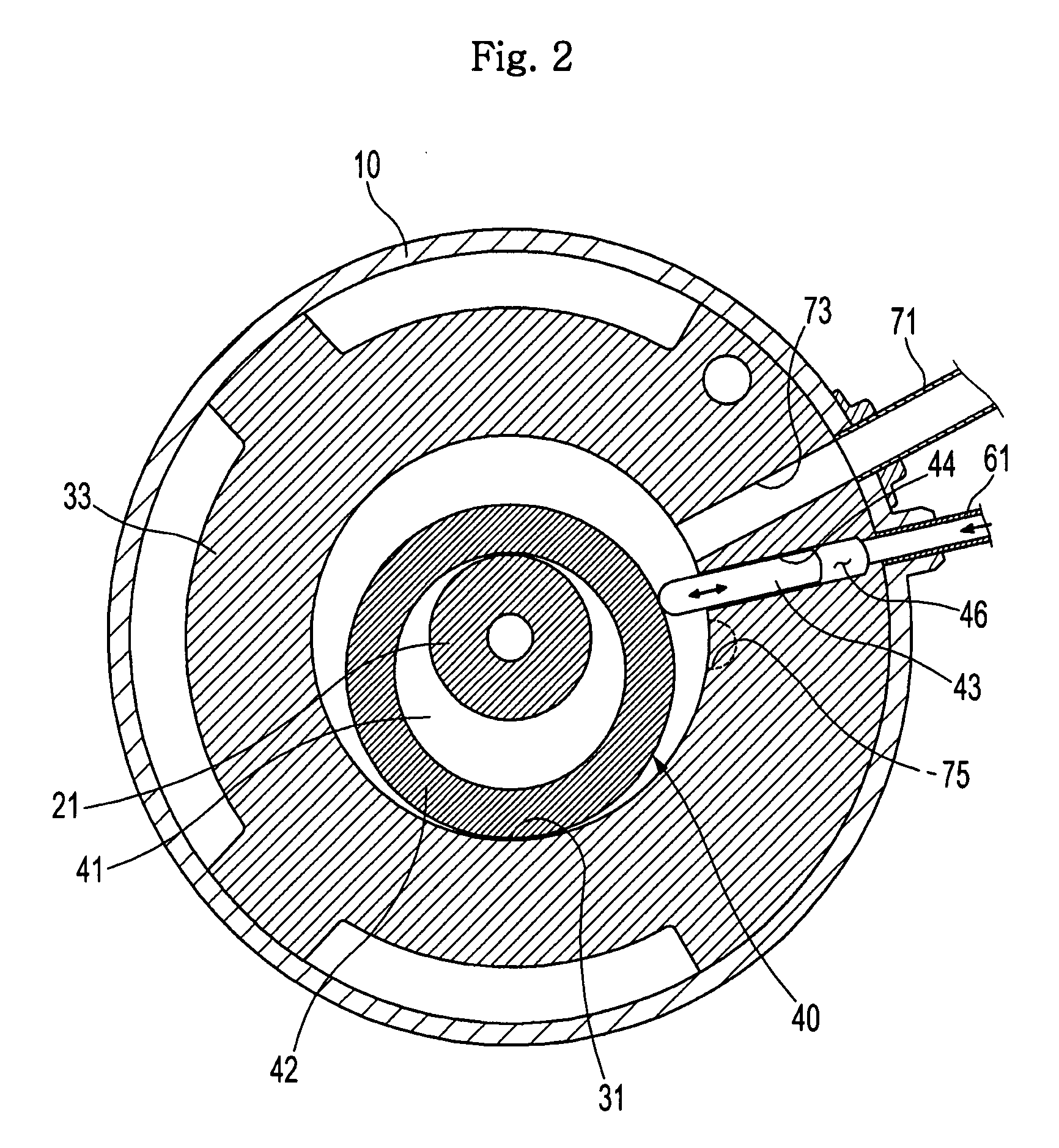
[0030]FIGS. 1 to 5 illustrate a rotary compressor in accordance with a first embodiment of the present invention. The rotary compressor, as shown in FIG. 1, includes a hermetic container 10, an electric motor device 20 arranged in an upper region of the hermetic container 10, and a compression device 30 arranged in a lower region of the hermetic container 10, the compression device 30 being connected to the electric motor device 20 by a rotating shaft 21.

[0031]The electric motor device 20 includes a cylindrical stator 22 attached to an inner surface of the hermetic container 10, and a rotor 23 rotatably mounted inside the stator 22, the rotor 23 being centrally coupled around the rotating shaf...


PUM


Abstract

A rotary compressor including a housing having first and second compressing chambers separated from each other, first and second flanges coupled to the housing, to close the first and second compressing chambers, respectively, an intermediate plate to separate the first and second compressing chambers from each other, first and second rollers rotatably installed in the first and second compressing chambers, respectively, first and second vanes to reciprocate in a radial direction of the first and second compressing chambers to divide the first and second compressing chambers, respectively, and a vane control device to control the reciprocating movement of the first vane by use of a suction pressure and a discharge pressure, for a variation in compression capacity. A first gap, defined at an end of the first roller, is smaller than a second gap defined at an end of the second roller.

Description

CROSS-REFERENCE TO RELATED APPLICATIONS[0001]This application claims the benefit of Korean Patent Application No. 10-2007-0015616, filed on Feb. 14, 2007 in the Korean Intellectual Property Office, the disclosure of which is incorporated herein by reference.BACKGROUND[0002]1. Field[0003]The present invention relates to a rotary compressor, and, more particularly, to a rotary compressor, which can improve the sealing effect of a compressing chamber and minimize the introduction of a refrigerant or oil into the compressing chamber while an idling-rotation operation is performed in the compressing chamber.[0004]2. Description of the Related Art[0005]Korean Patent Registration No. 10-0621026 (published on Sep. 15, 2006) discloses a multiple rotary compressor comprising: an upper first compressing chamber and a lower second compressing chamber separated from each other; and first and second rollers rotating in the respective compressing chambers to perform a compressing operation in the ...

Claims


Application Information

Patent Timeline
IPC IPC(8): F01C1/02
CPCF01C21/0863F04C11/001F04C28/185F04C23/001F04C27/005F04C18/3564F04C23/00F04C29/00
Inventor CHO, KYUNG RAECHANG, PHIL SOOSEO, HYEONG JOONLEE, IN JUCHOI, JI HOON
Owner SAMSUNG ELECTRONICS CO LTD
Why Eureka
Try Eureka