
Rail structure for window blinds

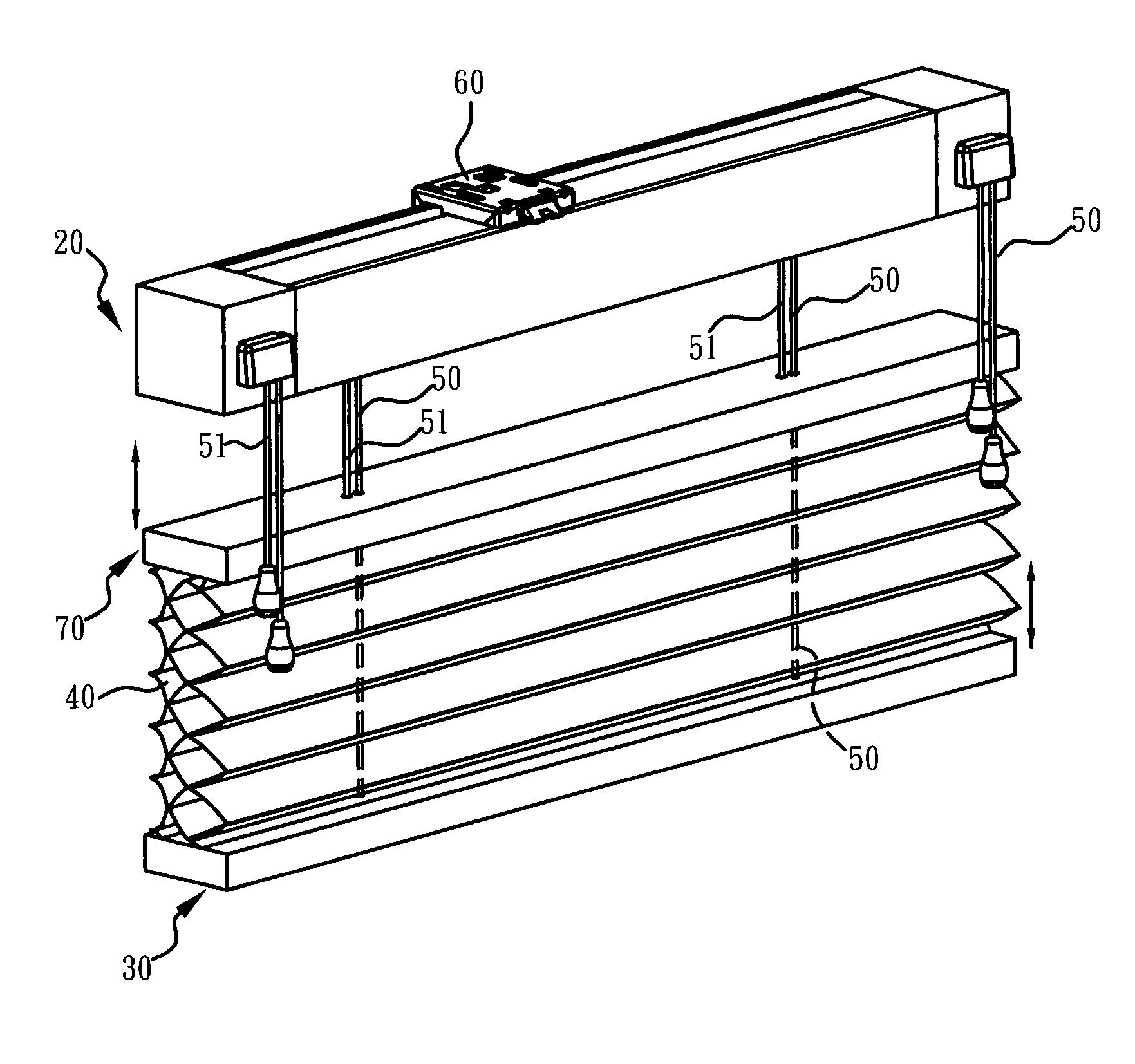
a technology for railings and window blinds, applied in door/window protective devices, construction, building components, etc., can solve the problems of gap between the valance and the headrail, inability to have an attractive appearance, and high total cost of manufacturing second and third arrangements, so as to enhance the overall aesthetic appearance of window blinds

Inactive Publication Date: 2008-08-21
NIEN MADE ENTERPRISE CO LTD
View PDF18 Cites 13 Cited by
  • Summary
  • Abstract
  • Description
  • Claims
  • Application Information

AI Technical Summary

Benefits of technology

The present invention provides a rail structure for window blinds, which enhances the overall aesthetic appearance for window blinds. The rail structure includes a headrail and a bottomrail connected by pulling cords. The headrail has a body with connecting members mounted on its front and back surfaces, and the bottomrail has a covering layer masked thereon. The rail structure is designed to be easily manufacturable and flexible in practical usage. The invention also provides advantages such as enhanced exterior appearance, increased product rigidity and lifetime, and reduced likelihood of damage or marring of the connecting members.

Problems solved by technology

However, this arrangement suffers from a disadvantage, the headrail and brackets are partially exposed; therefore, it can't have an attractive appearance.
Nevertheless, the total cost for manufacturing second and third arrangements are relatively higher, and they usually leave a gap between the valance and the headrail.

Method used


Image

  • Rail structure for window blinds
  • Rail structure for window blinds
  • Rail structure for window blinds

Examples


first embodiment

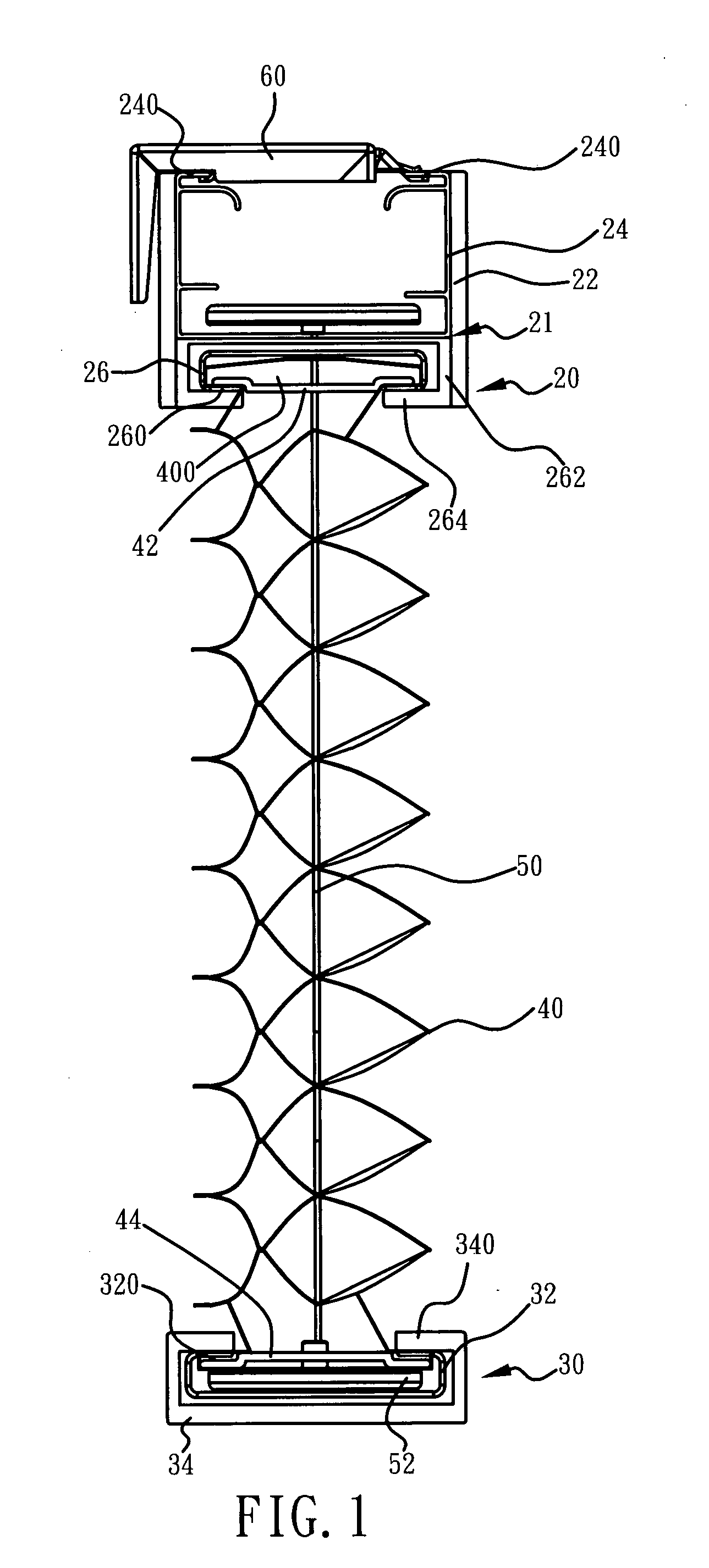
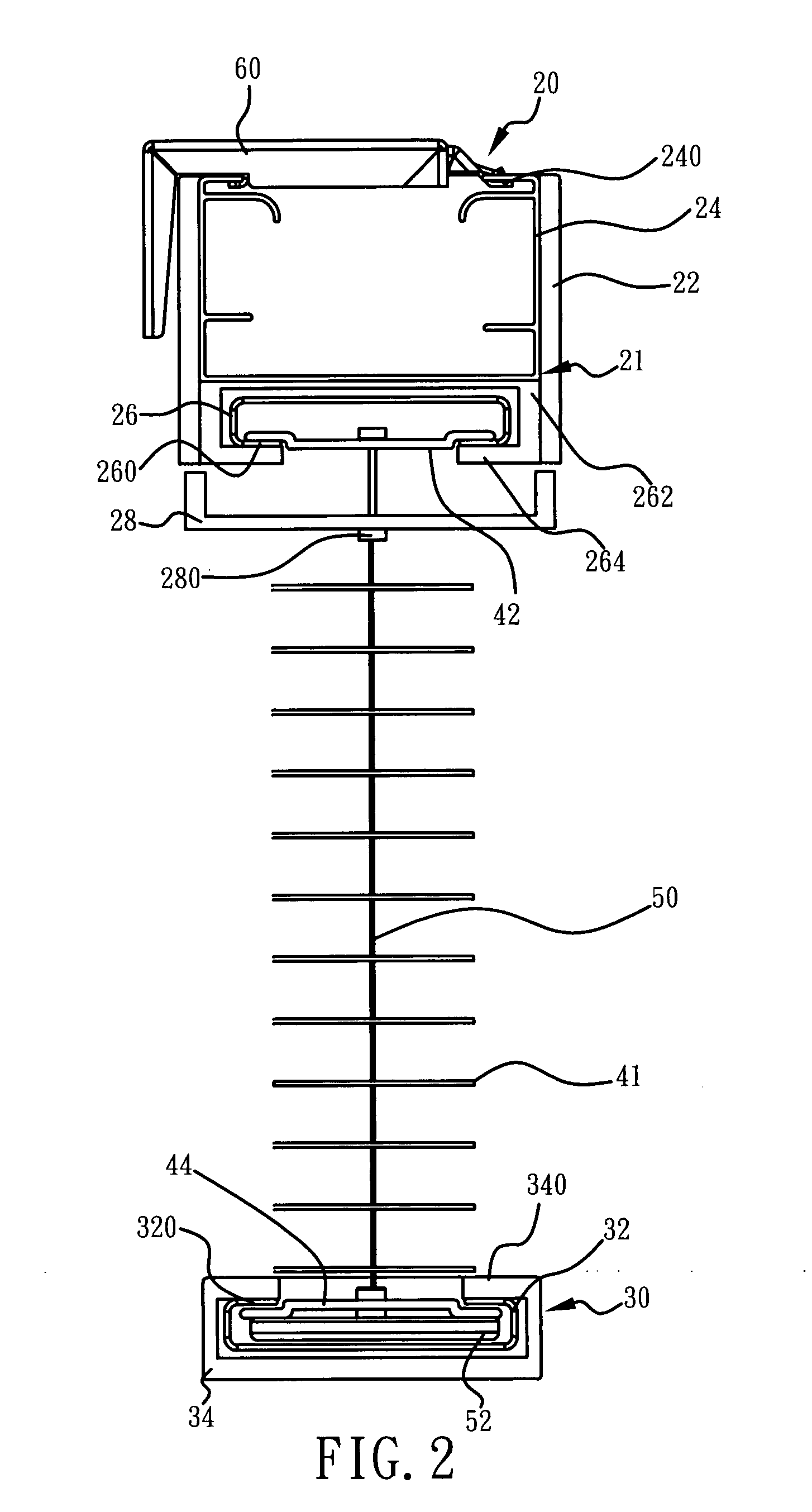
[0024]As shown in FIG. 1, it is a schematic structural view of the present invention. Cellular shades are taken as examples in this embodiment. The rail structure comprises a headrail 20, a bottomrail 30, and a cellular shade 40. The bottomrail is disposed below the headrail 20, and the cellular shade 40 is disposed between the headrail 20 and the bottomrail 30. In addition, a plurality of pulling cords 50 are connected to between the headrail 20 and the bottomrail 30 and substantially passing through the entire cellular shade 40, so as to control the upward and downward movement of the bottomrail 30 and thusly fix the position of the bottomrail 30 thereon.

[0025]The headrail 20 comprises a body 21 composed of a first supporting member 24 and a second supporting member 26, and a pair of connecting members 22 respectively mounted to a front surface and a back surface of the body 21.

[0026]The first supporting member 24 is disposed on an upper portion of the headrail 20 and has an upwar...

fourth embodiment

[0037]Referring to FIG. 5, it is a structure of a headrail of the present invention. The headrail 80 comprises a body 81 and a pair of connecting members 82. The boy has an H-shaped similarity, and a pair of first flanges 810 and a pair of second flanges 812 are inwardly extending into a predetermined width from respective top and bottom ends of two associated sides of the body 81. Still, the pair of connecting members 82 is respectively connected to front and rear surfaces of the body 81.

[0038]Besides, each bottommost end of the connecting member 82 has a fourth flange 820, and each fourth flange 820 is extending along the longitudinal orientation of the connecting member 82. Also, each fourth flange 820 has a predetermined width, so as to be fully concealed under the second flange 812; therefore, the body 81 made of metal materials would not be exposed.

[0039]Consequently, the supporting members (24, 26, 32, and 72) and the body 81, that are made of metal materials, can bear the ov...


PUM


Abstract

A rail structure for window blinds is provided, which includes a body and at least one connecting member. The body has a pair of first flanges and a pair of second flanges. The first flanges are disposed on tops of two sides of the body, and the second flanges are disposed on bottoms of the two sides of the body. In addition, the connecting member is mounted to an outer surface of one side of the body, has a predetermined shape of constant cross-section profile, a length and a width, Besides, a flange is disposed on a predetermined position of the connecting member and extending to one side of the body. By the connecting members, the headrail appearance can be enhanced. Moreover, as the connecting members do not directly bear the overall or partial weight of the window blind, the rail structure can have an extended product lifetime.

Description

[0001]This application claims the benefit of P.R.China patent application No. 200720005768.3, filed on Feb. 15, 2007 and P.R.China patent application No. 200720150896.7, filed on Jul. 12, 2007, which are hereby incorporated by reference for all purposes as if fully set forth herein.BACKGROUND OF THE INVENTION[0002]1. Field of Invention[0003]The present invention relates to a rail structure for window blinds, and more particularly, to a rail structure having decorative outerlayers.[0004]2. Related Art[0005]According to prior arts, window blinds normally include a headrail and a bottomrail. The bottomrail is disposed below the headrail and controlled by means of pulling cords to move in a vertically upward or downward motion. The blind slat is disposed between the headrail and the bottomrail, and it can be stacked, extended, or tilted in accordance to the movement of the bottomrail.[0006]The window blinds usually are fastened on walls or ceiling by brackets. For adding aesthetic appea...

Claims


Application Information

Patent Timeline
Patent Type & Authority Applications(United States)
IPC IPC(8): E06B9/266E06B9/24
CPCE06B9/323
Inventor NIEN, MINGWEN, YU-CHECHENG, JU-SHENGCHIU, OLIVER
Owner NIEN MADE ENTERPRISE CO LTD
Learn More