Eureka AIR delivers breakthrough ideas for toughest innovation challenges, trusted by R&D personnel around the world.

Computer housing

Inactive Publication Date: 2008-08-21
COMPUCASE ENTERPRISE
View PDF13 Cites 0 Cited by
  • Summary
  • Abstract
  • Description
  • Claims
  • Application Information

AI Technical Summary

Benefits of technology

[0007]Therefore, the object of the present invention is to provide a computer housing that can overcome the aforesaid drawback associated with the prior art.
[0008]Accordingly, a computer housing of this invention comprises: a housing body defining an inner space therein; a first supporting plate mounted in the inner space in the housing body; a second supporting plate mounted in the inner space in the housing body, parallel to the first supporting plate, and cooperating with the first supporting plate to define amounting space therebetween, the mounting space being adapted to receive a box-like device that is formed with an engaging hole, the second supporting plate being formed with first and second through-holes; and an operating lever having first and second end portions and a middle portion that extends between the first and second end portions and that is pivoted to the second supporting plate. The middle portion has opposite first and second ends. The first end portion extends and is bent from the first end of the middle portion. The first end of the middle portion is formed with an engaging tongue that extends into the first through-hole in the second supporting plate. The second end portion is bent and extends from the second end of the middle portion into the second through-hole in the second supporting plate. The operating lever is rotatable relative to the second supporting plate between a first angular position, in which the second end portion of the operating lever is disposed outside of the mounting space and in which the engaging tongue extends through the first through-hole in the second supporting plate and into the mounting space and is adapted to engage the engaging hole in the box-like device, thereby preventing removal of the box-like device from the computer housing, and a second angular position, in which the second end portion of the operating lever extends through the second through-hole in the second supporting plate and into the mounting space, and in which the engaging tongue is disposed outside of the mounting space and is disengaged from the engaging hole in the box-like device, thereby permitting removal of the box-like device from the computer housing.

Problems solved by technology

However, securing of the box-like device 2 to the computer housing 1 using the fasteners 14 is relatively inconvenient.

Method used


Image

  • Computer housing
  • Computer housing
  • Computer housing

Examples


Embodiment Construction

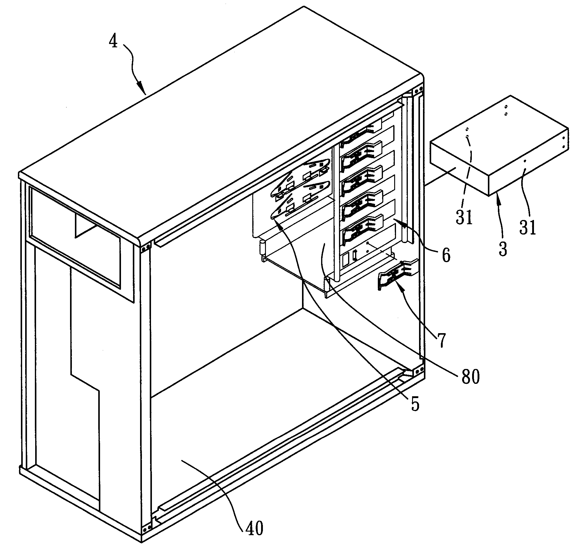
[0017]Referring to FIGS. 4 to 7, the preferred embodiment of a computer housing according to the present invention is shown to include: a housing body 4 defining an inner space 40 therein; a first supporting plate 5 mounted in the inner space 40 in the housing body 4; a second supporting plate 6 mounted in the inner space 40 in the housing body 4, parallel to the first supporting plate 5, and cooperating with the first supporting plate 5 to define a mounting space 80 therebetween, the mounting space 80 being adapted to receive a box-like device 3 that is formed with upper and lower engaging holes 31 in two lateral sides thereof, the second supporting plate 6 being formed with upper and lower first through-holes 64 and a second through-hole 63; and an operating lever 7 having first and second end portions 76, 78 and a middle portion 71 that extends between the first and second end portions 76, 78 and that is pivoted to the second supporting plate 6. The middle portion 71 of the opera...


PUM


Abstract

A computer housing includes: a housing body; a first supporting plate mounted in the housing body; a second supporting plate mounted in the housing body and cooperating with the first supporting plate to define a mounting space therebetween; and an operating lever pivoted to the second supporting plate, formed with an engaging tongue, and rotatable relative to the second supporting plate between a first angular position, in which the engaging tongue extends into the mounting space for retaining a box-like device in the mounting space, and a second angular position, in which the engaging tongue is disposed outside of the mounting space for permitting removal of the box-like device.

Description

BACKGROUND OF THE INVENTION[0001]1. Field of the Invention[0002]The invention relates to a computer housing, more particularly to a computer housing including an operating lever for retaining releasably a box-like device in the computer housing.[0003]2. Description of the Related Art[0004]Data-storing or read / write devices are usually box-like in shape and are to be mounted in a computer housing. Threaded holes are formed in lateral sides of the devices for extension of fasteners therein so as to permit fastening of the devices to the computer housing.[0005]FIGS. 1 and 2 illustrate a conventional computer housing 1 adapted for mounting at least one box-like device 2 that has lateral sides formed with a plurality of threaded holes 21 therein. The computer housing 1 includes a housing body 11, a first supporting plate 12 mounted to the housing body 11 and a second supporting plate 13 mounted to the housing body 11 and disposed opposite to the first supporting plate 12. The first suppo...

Claims


Application Information

Patent Timeline
IPC IPC(8): A47B96/00
CPCG11B33/128G06F1/187
Inventor CHOU, I-CHINGLIN, CHIH-WEIHUANG, YUH-WEN
Owner COMPUCASE ENTERPRISE
Why Eureka
Eureka Blog
Learn More