
Composite illumination module

a technology of illumination module and composite material, which is applied in the direction of fixed installation, lighting and heating apparatus, light source combination, etc., can solve the problems of high electricity consumption, still a drawback of the lamp associated with the motion sensor, and dark environment, and achieve the effect of saving electricity consumption

Inactive Publication Date: 2008-08-21
CHEN CHIA TEH
View PDF9 Cites 13 Cited by
  • Summary
  • Abstract
  • Description
  • Claims
  • Application Information

AI Technical Summary

Benefits of technology

[0007]The primary object of the present invention is to provide a composite illumination module which provides an indicative or guiding effect at a far distance while providing a common illumination at a close distance, thereby saving electricity consumption.
[0009]The first light-emitting element may be a bulb, and the second light-emitting element is a light-emitting diode with low wattage and low electricity consumption.
[0010]The present invention has the following effects. The second light-emitting element having a low wattage and low electricity consumption can provide an indicative or guiding effect at a far distance, so that a person can recognize their surroundings. Thus, accidents caused by insufficient light can be avoided. Further, when a person approaches, the second light-emitting element can be switched to the first light-emitting element having a higher wattage and intensity, thereby providing high-intensity illumination at a close distance. With the permanent illumination of the second light-emitting element having a feature of low wattage and low electricity consumption, energy is constantly saved.

Problems solved by technology

Most lamps use conventional incandescent bulbs, they consume a lot of electricity after long-term use, increasing power bills spending for government, business and homes.
However, according to practical experience, there is still a drawback existing in the lamp associated with the motion sensor.
Therefore, the surrounding environment is dark and the person cannot recognize their surroundings.
As a result, frequent accidents happen.

Method used


Image

  • Composite illumination module
  • Composite illumination module
  • Composite illumination module

Examples


Embodiment Construction

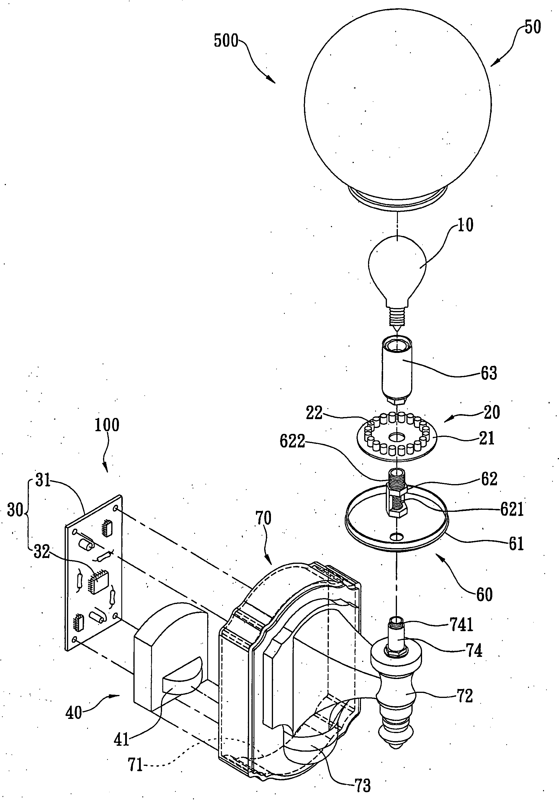
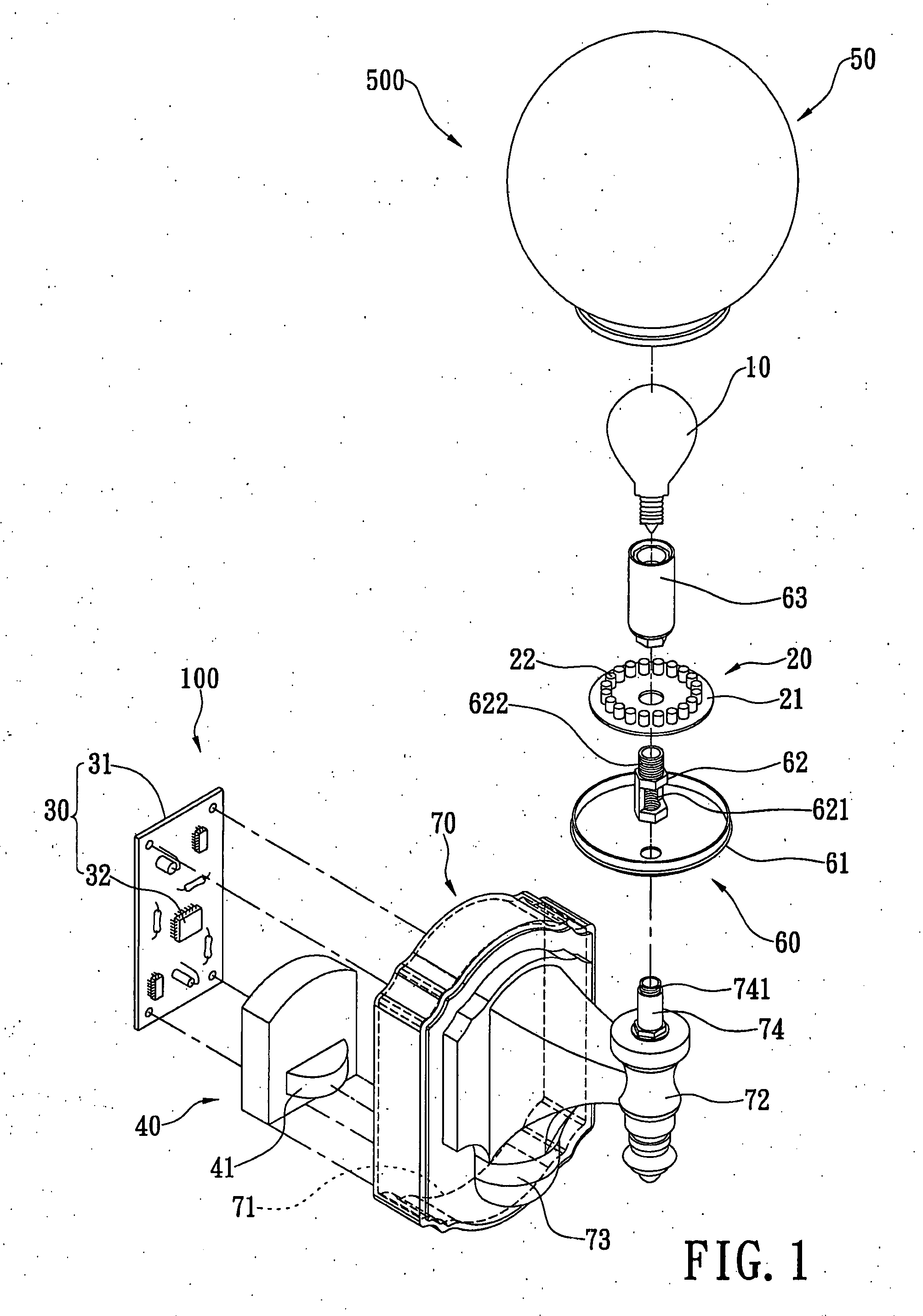
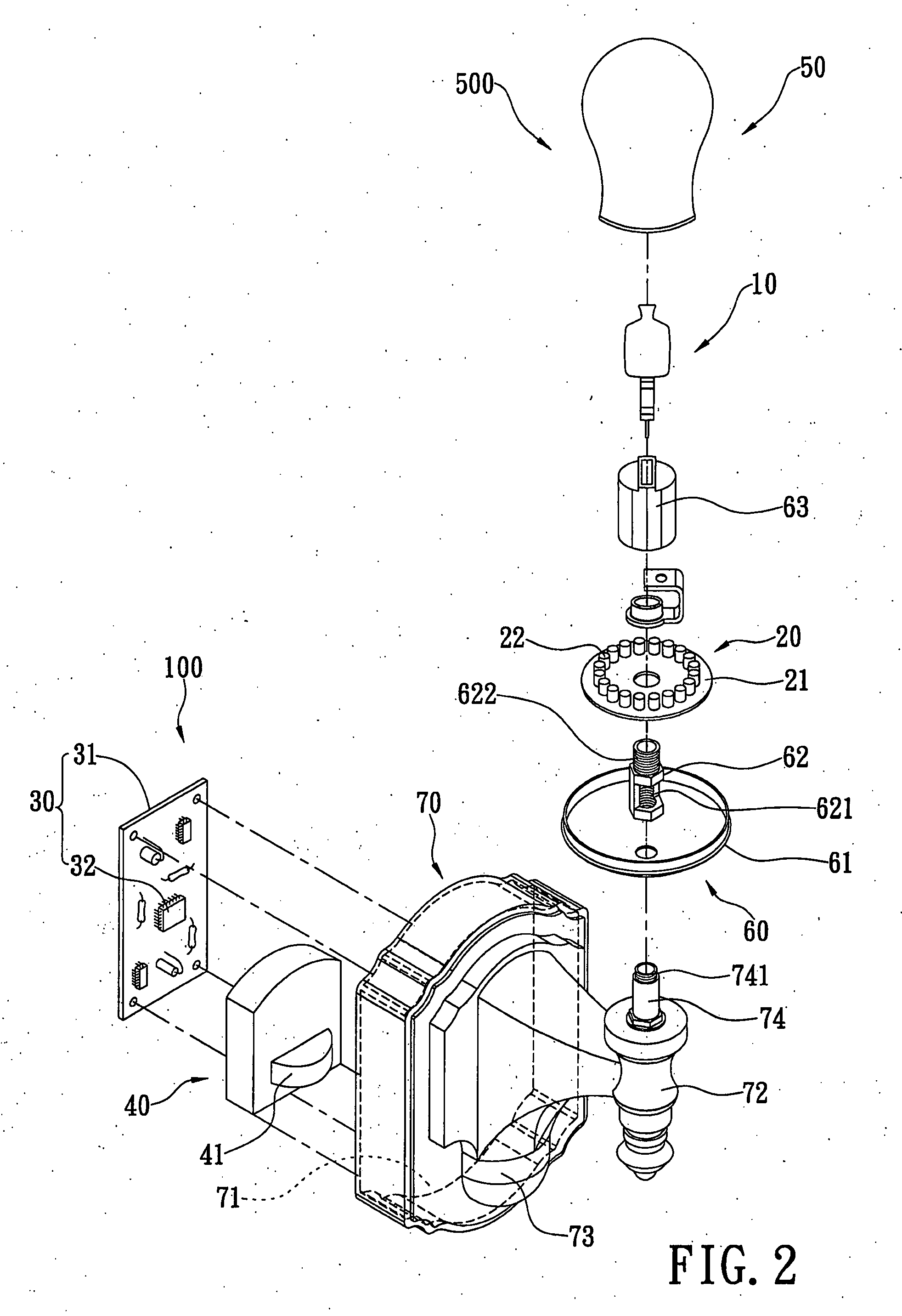
[0020]With reference to FIG. 1 the first embodiment of the present invention is shown. The present invention provides a composite illumination module 100, which comprises at least one light-emitting element 10, a light-emitting unit 20, and a control circuit assembly 30. Further, the present invention can comprise a motion sensor 40.

[0021]Light-emitting unit 20 has a circuit board 21 and at least a second light-emitting element 22 electrically connected on the circuit board 21. The control circuit assembly 30 has a control circuit board 31 and a plurality of electronic elements 32 (such as a resistor, a capacitor and a control IC) assembled on the control circuit board 31.

[0022]The control circuit assembly 30 is electrically connected to the first light-emitting element 10 and light-emitting unit 20. The motion sensor 40 is electrically connected to the control circuit assembly 30. In addition, when the first light-emitting element 10 emits light, the intensity (wattage) thereof is ...


PUM


Abstract

A composite illumination module includes at least one first light-emitting element, a light-emitting unit, and a control circuit assembly, and further has a motion sensor. The light-emitting unit has a circuit board and at least one second light-emitting element electrically connected with the circuit board. The wattage and the intensity of the first light-emitting element are higher than those of the second light-emitting element. The control circuit assembly is electrically connected with the first light-emitting element and the light-emitting unit so as to electrically control the first and second light-emitting elements to selectively emit light. The motion sensor is electrically connected with the control circuit assembly. With this arrangement, the present invention can provide an indicative or guiding effect at a far distance, and provide a common illumination at a close distance using less electricity than in prior art models.

Description

BACKGROUND OF THE INVENTION[0001]1. Field of the Invention[0002]The present invention relates to a composite illumination module, and in particular to an illumination module in which the luminous intensity thereof is changeable.[0003]2. Description of Related Art[0004]Most lamps use conventional incandescent bulbs, they consume a lot of electricity after long-term use, increasing power bills spending for government, business and homes. Therefore, in order to reduce electricity consumption and improve safety, many manufacturers connect the lamp with a motion sensor. When the motion sensor detects the approach of a person or other creatures, the lamp will automatically turn on. After a period in which no more movement is further detected, the lamp will automatically turn off, thereby avoiding the unnecessary consumption of electricity when illumination is no longer needed.[0005]However, according to practical experience, there is still a drawback existing in the lamp associated with t...

Claims


Application Information

Patent Timeline
IPC IPC(8): H05B39/04
CPCF21S8/033F21V23/0442F21W2131/10F21Y2103/022F21Y2113/00F21Y2113/02F21Y2101/00F21Y2101/02F21Y2103/33F21Y2113/20F21Y2115/10
Inventor CHEN, CHIA-TEH
Owner CHEN CHIA TEH
Learn More