Circuits and methods for battery charging

a battery pack and circuit technology, applied in the direction of electric vehicles, secondary cell servicing/maintenance, transportation and packaging, etc., can solve the problems of shortening the battery life, affecting the battery life, and the charging current provided by the ac to dc converter b>200/b> may have negative effects on the battery li

Active Publication Date: 2008-08-21
O2 MICRO INT LTD
View PDF4 Cites 133 Cited by
  • Summary
  • Abstract
  • Description
  • Claims
  • Application Information

AI Technical Summary

Benefits of technology

[0011]Embodiments in accordance with the present invention provide a battery charging circuit. The battery charging circuit comprises an AC to DC converter, a charging control switch, and a charger controller. The AC to DC converter provides a charging power to a battery pack. The charging control switch is coupled between the AC to DC converter and the battery pack. The charging control switch

Problems solved by technology

However, the pulse type charger controller 112 utilized herein is typically complicated and expensive.
However, when the battery pack 110 has been deeply discharged, the charging current provided by the AC to DC converter 200 may have negative effects on the battery life.
Additionally, if the AC power source 102 is unstable the DC voltage will also be unstable, which can also shorten the batter

Method used


Image

  • Circuits and methods for battery charging
  • Circuits and methods for battery charging
  • Circuits and methods for battery charging

Examples


Embodiment Construction

[0020]Reference will now be made in detail to embodiments of the present invention. While the invention will be described in conjunction with the embodiments, it will be understood that they are not intended to limit the invention to these embodiments. On the contrary, the invention is intended to cover alternatives, modifications and equivalents, which may be included within the spirit and scope of the invention as defined by the appended claims.

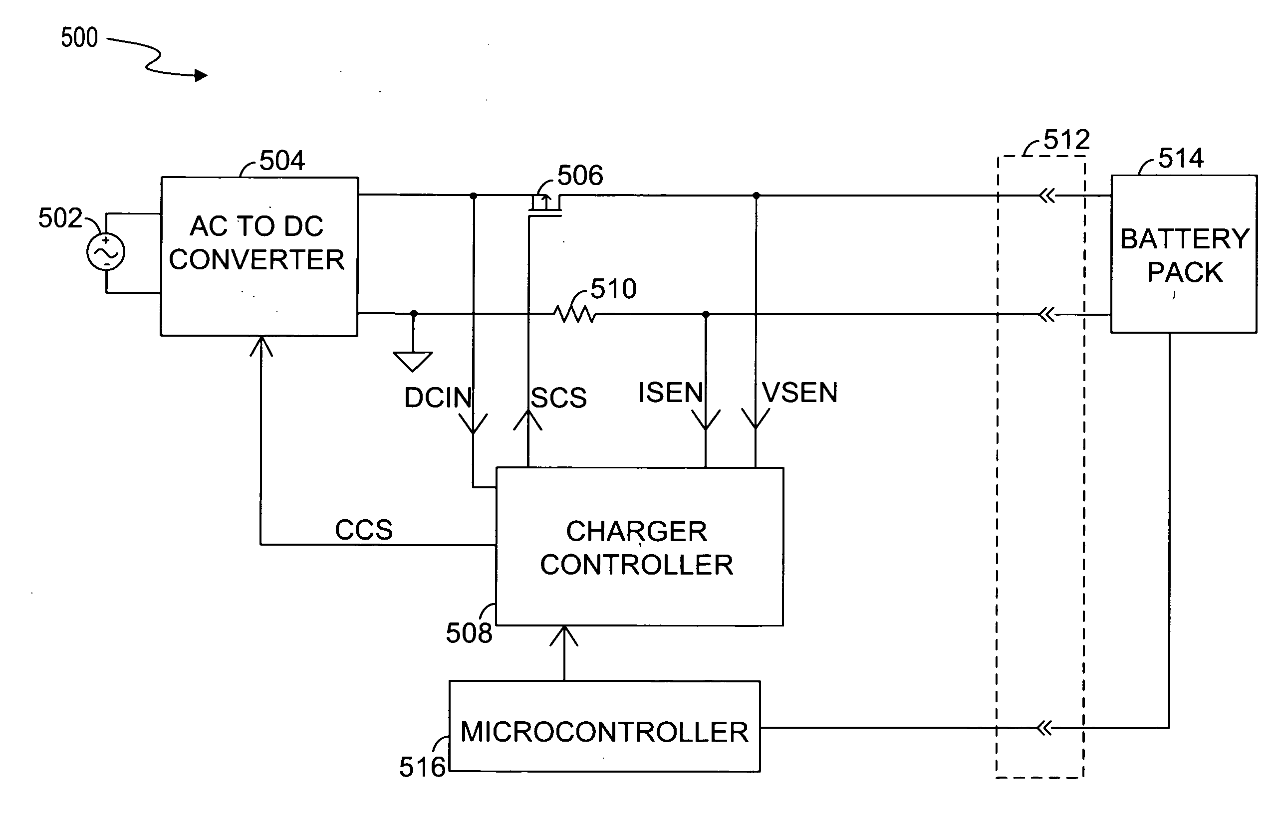
[0021]FIG. 5 illustrates a block diagram of a battery charging circuit 500, in accordance with one embodiment of the present invention. The battery charging circuit 500 includes an AC power source 502, an AC to DC converter (controllable power converter) 504, a charging control switch 506, a charger controller 508, a current sensing resistor 510, a slide connector 512, and a battery pack 514, in one embodiment. The AC to DC converter 504 receives an AC power of the AC power source 502 and provides a charging power (e.g., regulated DC voltag...


PUM


Abstract

Circuits and methods for battery charging are disclosed. In one embodiment, the battery charging circuit comprises an AC to DC converter, a charging control switch, and a charger controller. The AC to DC converter provides a charging power to a battery pack. The charging control switch is coupled between the AC to DC converter and the battery pack. The charging control switch transfers the charging power to the battery pack. The charger controller detects a battery status of the battery pack and controls the charging control switch to charge the battery pack in a continuous charging mode or a pulse charging mode according to the battery status. The charger controller also controls the AC to DC converter to regulate the charging power according to the battery status.

Description

RELATED APPLICATION[0001]This application claims priority to U.S. Provisional Application No. 60 / 901,755, filed on Feb. 16, 2007, the specification of which is hereby incorporated in its entirety by reference.BACKGROUND[0002]1. Field of the Invention[0003]The present invention relates to circuits and methods for charging a battery pack.[0004]2. Description of the Related Art[0005]FIG. 1 illustrates a block diagram of a conventional battery charging circuit 100. The conventional battery charging circuit 100 includes an alternating current (AC) power source 102, an alternating current (AC) to direct current (DC) converter 104, a switch 106, a pulse type charger controller 112, and a battery pack 110. The AC power source 102 provides an AC voltage. The AC to DC converter 104 converts the AC voltage to a DC voltage. The DC voltage is provided to the battery pack 110 through the switch 106. The switch 106 is switched on and off by the pulse type charger controller 112, such that current ...

Claims


Application Information

Patent Timeline
IPC IPC(8): H02J7/04H01M10/44
CPCH01M10/44H02J7/045H02J7/0093H02J7/00711Y02E60/10H02J7/04H02J7/00714H02J7/007182
Inventor HARTULAR, ALEXCARAGHIORGHIOPOL, EFTIMIESIMION, DAN
Owner O2 MICRO INT LTD
Why Eureka
Try Eureka