Acoustic wave touch actuated system

a technology of actuation system and touch, which is applied in the direction of electronic switching, pulse technique, instruments, etc., can solve the problems of inability to distinguish between pressure levels and adverse effects of capacitive sensors

Inactive Publication Date: 2008-08-21
TEXZEC
View PDF9 Cites 74 Cited by
  • Summary
  • Abstract
  • Description
  • Claims
  • Application Information

AI Technical Summary

Benefits of technology

[0005]Embodiments of the present invention provide an improved system and method of detecting pressure and movement over a surface, such as may be used, for example, with respect to a computer (e.g., a touch or mouse pad of a laptop computer), and various other applications.

Problems solved by technology

However, capacitive sensors may be adversely affected by water or other such fluids on the surface of the touch or mouse pad.
Additionally, conventional capacitive sensors are not able to distinguish between pressure levels.

Method used


Image

  • Acoustic wave touch actuated system
  • Acoustic wave touch actuated system
  • Acoustic wave touch actuated system

Examples


Embodiment Construction

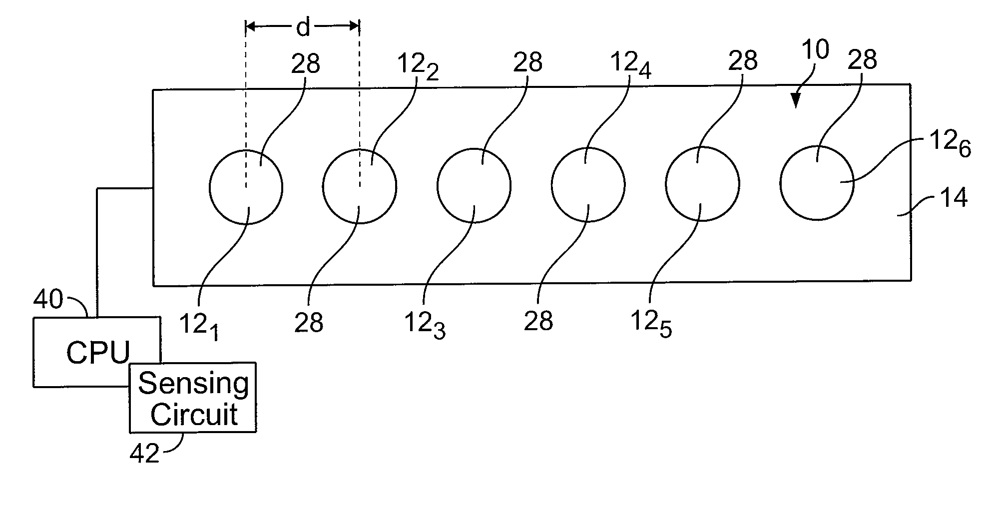
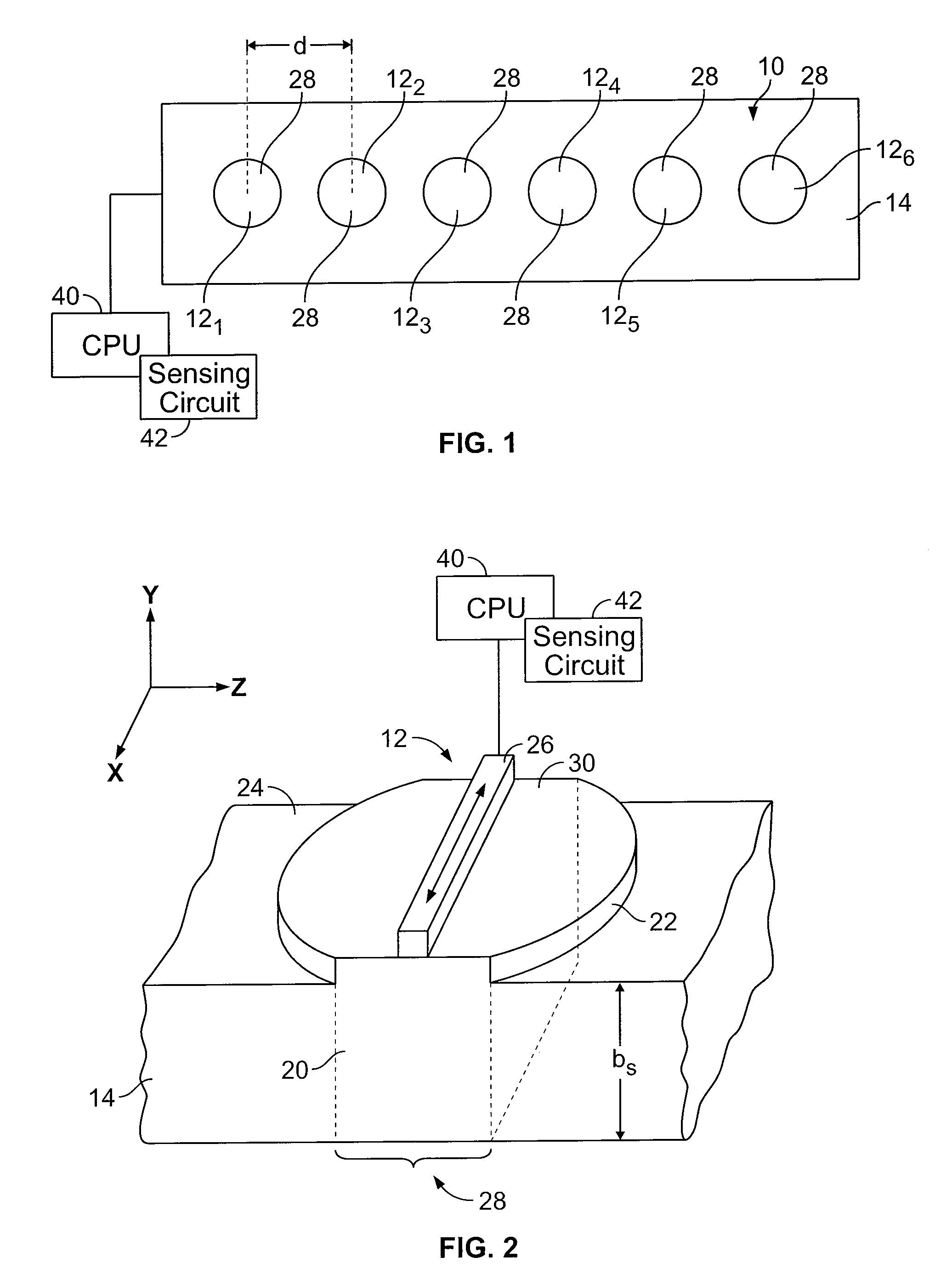
[0018]FIG. 1 illustrates a top plan view of a linear slider pad 10 according to an embodiment of the present invention. The slider pad 10 includes a plurality of acoustic wave switches 12 formed on or within a substrate 14. Each acoustic wave switch 12 may include respective indicia that identifies the position of a particular switch 12. The substrate 14 and the acoustic wave switches 12 may be formed of any material such as metal, plastic, glass, ceramic, or the like, in which an acoustic wave may propagate.

[0019]FIG. 2 illustrates a side cross-sectional view of an acoustic wave switch 12. Each acoustic wave switch 12 has an associated acoustic wave cavity, or resonator 20 that extends through the thickness bs of the substrate 14. The acoustic wave cavity 20 is formed in the substrate 14 such that the mass per unit surface area of the acoustic wave cavity 20 is greater than the mass per unit surface area of the substrate 14 adjacent the acoustic wave cavity 20. In one embodiment, t...


PUM


Abstract

A touch pad assembly includes a substrate and a plurality of acoustic wave switches positioned with respect to the substrate. Each of the plurality of acoustic wave switches includes a touch surface connected to an acoustic wave cavity and a transducer secured to the acoustic wave cavity. The plurality of acoustic wave switches are positioned to provide detection of sliding motion direction and rate between the plurality of acoustic wave switches.

Description

RELATED APPLICATIONS[0001]This application relates to and claims priority benefits from U.S. Provisional Patent Application No. 60 / 902,278 entitled “Acoustic Wave Touch Actuated System,” filed Feb. 20, 2007, which is hereby incorporated by reference in its entirety.FIELD OF THE INVENTION[0002]Embodiments of the present invention generally relate to an acoustic wave touch actuated system and more particularly to an acoustic wave touch actuated system that may be used to detect motion, including direction and speed, over a surface of a device.BACKGROUND OF THE INVENTION[0003]Capacitive slider assemblies and laptop computer touch or mouse pads are currently configured to detect sliding motion. For example, an operator may slide a finger across the touch or mouse pad, and a processing unit within the laptop correlates that motion with respect to images shown on the screen of the laptop computer. Thus, as a user moves a finger over the touch or mouse pad, a cursor displayed on the screen...

Claims


Application Information

Patent Timeline
Patent Type & Authority Applications(United States)
IPC IPC(8): G06F3/043
CPCG06F3/043H03K2217/96015H03K2217/96011H03K17/96
Inventor KNOWLES, TERRENCE J.BREMIGAN, CHARLES F.WEHRER, WAYNE J.
Owner TEXZEC
Why Eureka
Try Eureka