Image filling methods

a filling method and image technology, applied in the field of image filling methods, can solve the problems of inability to obtain a complete image of a target object, considerable interference in digital image preservation, and inability to complete images

Inactive Publication Date: 2008-08-21
IND TECH RES INST
View PDF14 Cites 11 Cited by
  • Summary
  • Abstract
  • Description
  • Claims
  • Application Information

AI Technical Summary

Problems solved by technology

Target objects or scenes, such as buildings, historic monuments, large-scale landscapes and devices, may be obstructed by unwanted objects during image capture thereof, resulting in incomplete images.
In this case, no complete image of a target object can be obtained even if images of the target object are captured from various angles.
The unwanted obstructions can create considerable interference in digital image preservation and 3D model construction for historic monuments and buildings.
However, blur may be generated for images including large area targets.
Since the image inpainting is still based on other areas of image, the result may be also undesirable.

Method used


Image

  • Image filling methods
  • Image filling methods
  • Image filling methods

Examples


Embodiment Construction

[0026]Image filling methods are provided.

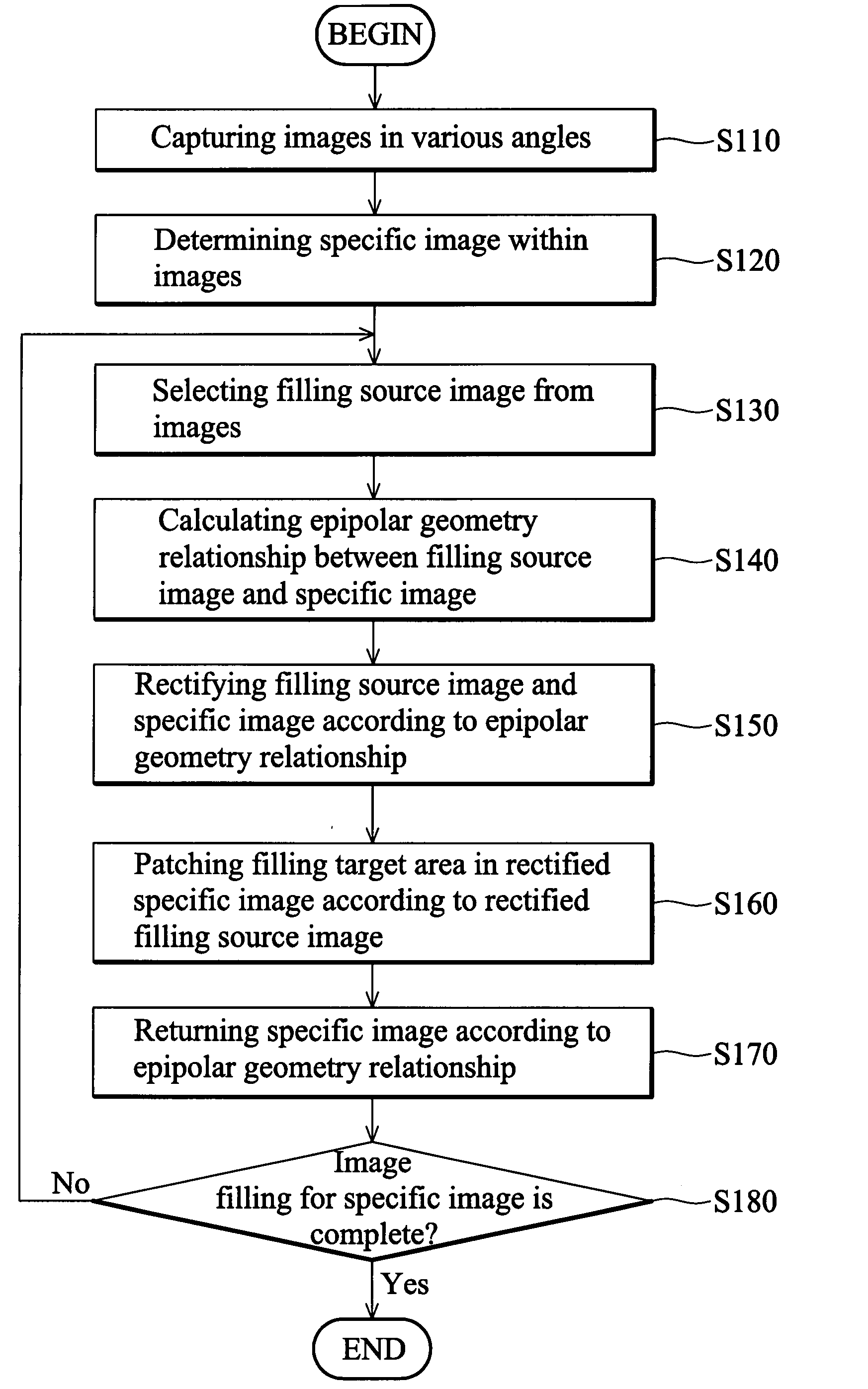
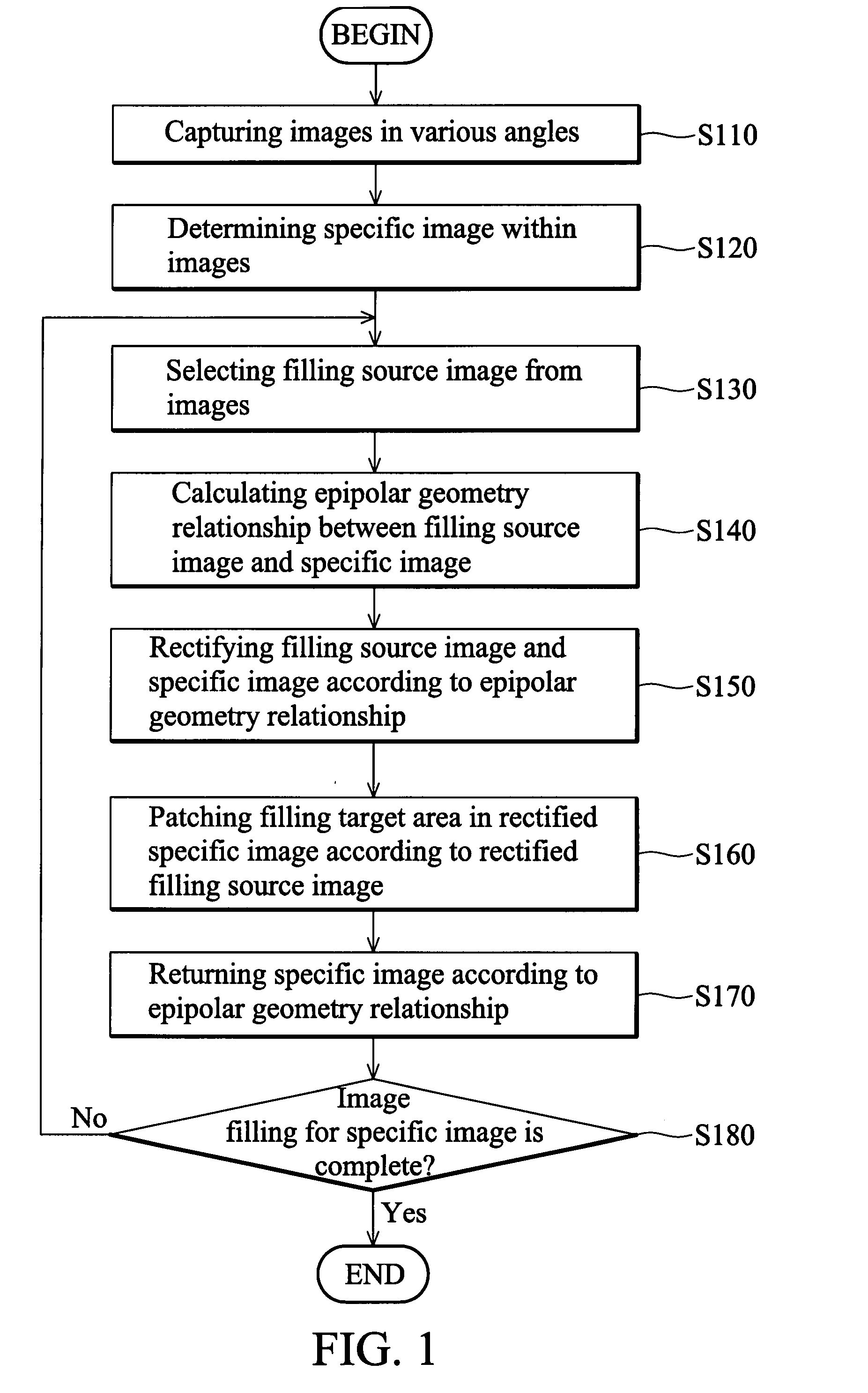
[0027]FIG. 1 is a flowchart of an embodiment of an image filling method.

[0028]In step S110, a plurality of images corresponding to a target object or a scene in 3D space is captured at various angles using a video camera or a digital camera. In step S120, a specific image is determined from the images, and in step S130, a filling source image is selected from the rest of the images. The specific image is the image to be patched, and the filling source image can be used to patch filling targets in the specific image. In step S140, an epipolar geometry relationship between the filling source image and the specific image is calculated.

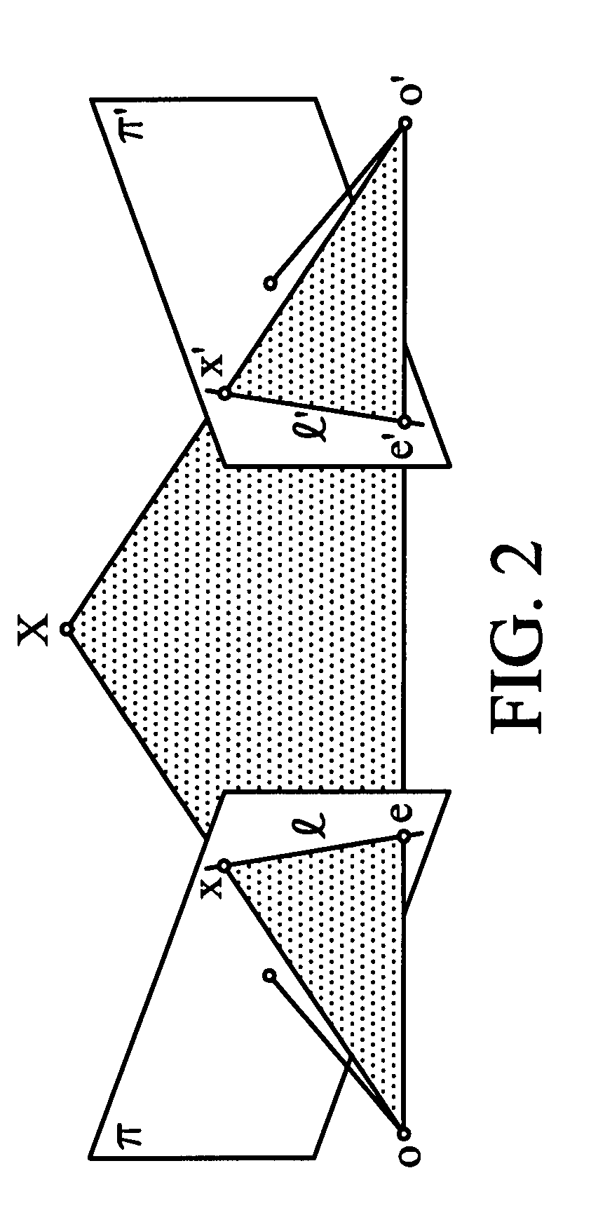
[0029]Epipolar geometry is the internal projection geometry relationship between two images. A fundamental matrix is used to represent the epipolar geometry relationship between two images. The epipolar geometry relationship is based on the intersections of a plane through a baseline and two image planes. It is ass...


PUM


Abstract

Image filling methods. A plurality of images corresponding to a target object or a scene are captured at various angles. An epipolar geometry relationship between a filling source image and a specific image within the images is calculated. The filling source image and the specific image are rectified according to the epipolar geometry relationship. At least one filling target area in the rectified specific image is patched according to the rectified filling source image.

Description

BACKGROUND OF THE INVENTION[0001]1. Field of the Invention[0002]The disclosure relates generally to image filling methods, and, more particularly to image filling methods using epipolar geometry relationships between images in different capturing angles.[0003]2. Description of the Related Art[0004]Target objects or scenes, such as buildings, historic monuments, large-scale landscapes and devices, may be obstructed by unwanted objects during image capture thereof, resulting in incomplete images. Some obstructions may be automatically removed, such as vehicles or pedestrians, while others, such as signboards, signs, trees or other buildings, cannot. In this case, no complete image of a target object can be obtained even if images of the target object are captured from various angles. The unwanted obstructions can create considerable interference in digital image preservation and 3D model construction for historic monuments and buildings.[0005]Manuel M. Oliverira proposed an inpainting...

Claims


Application Information

Patent Timeline
Patent Type & Authority Applications(United States)
IPC IPC(8): G06K9/46G06V10/147
CPCG06K9/209G06T11/40G06T7/0022G06T5/005G06T7/97G06V10/147
Inventor CHEN, CHIA-CHENTANG, CHENG-YUANWU, YI-LEHLIU, CHI-TSUNG
Owner IND TECH RES INST
Why Eureka
Try Eureka