Automated control of boom and attachment for work vehicle

a technology for work vehicles and booms, applied in the direction of electric programme control, program control, instruments, etc., can solve the problems of reducing the longevity of hydraulic cylinders and other components, affecting the operation of work vehicles, and causing abrupt or jerky movements

Active Publication Date: 2008-08-21
DEERE & CO
View PDF65 Cites 19 Cited by
  • Summary
  • Abstract
  • Description
  • Claims
  • Application Information

AI Technical Summary

Problems solved by technology

Where limit switches or two-state position sensors are used to control the motion of the boom or attachment, the work vehicle may produce abrupt or jerky movements in automated positioning of the boom or attachment.
The abrupt or jerky movements produce unwanted vibrations and shock that tend to reduce the longevity of hydraulic cylinders and other components.
Further, the abrupt or jerky movements may annoy an operator of the equipment.
However, the control system may not be configured to align a boom to a desired boom height.

Method used


Image

  • Automated control of boom and attachment for work vehicle
  • Automated control of boom and attachment for work vehicle
  • Automated control of boom and attachment for work vehicle

Examples


first embodiment

[0041]FIG. 6 relates to a method for controlling a boom and attachment of a work vehicle. The method of FIG. 6 begins in step S300.

[0042]In step S300, a user interface 22 or controller 20 establishes a ready position associated with at least one of a target boom angular range (e.g., target boom angle subject to an angular tolerance) of a boom and a target attachment angular range (e.g., a target attachment angle subject to an angular tolerance) of an attachment. The target boom angular range may be bounded by a lower boom angle and an upper boom angle. Because any boom angle within the target boom angular range is acceptable, the controller 20 has the possibility or flexibility of (a) decelerating the boom 252 within at least a portion of the target boom angular range (or over an angular displacement up to a limit of the target boom angular range) to achieve a desired boom motion curve (e.g., reference boom curve or compensated boom curve segment), and / or (b) shifting a stopping poi...

second embodiment

[0051]FIG. 7 relates to a method for controlling a boom and attachment of a work vehicle. The method of FIG. 7 begins in step S400.

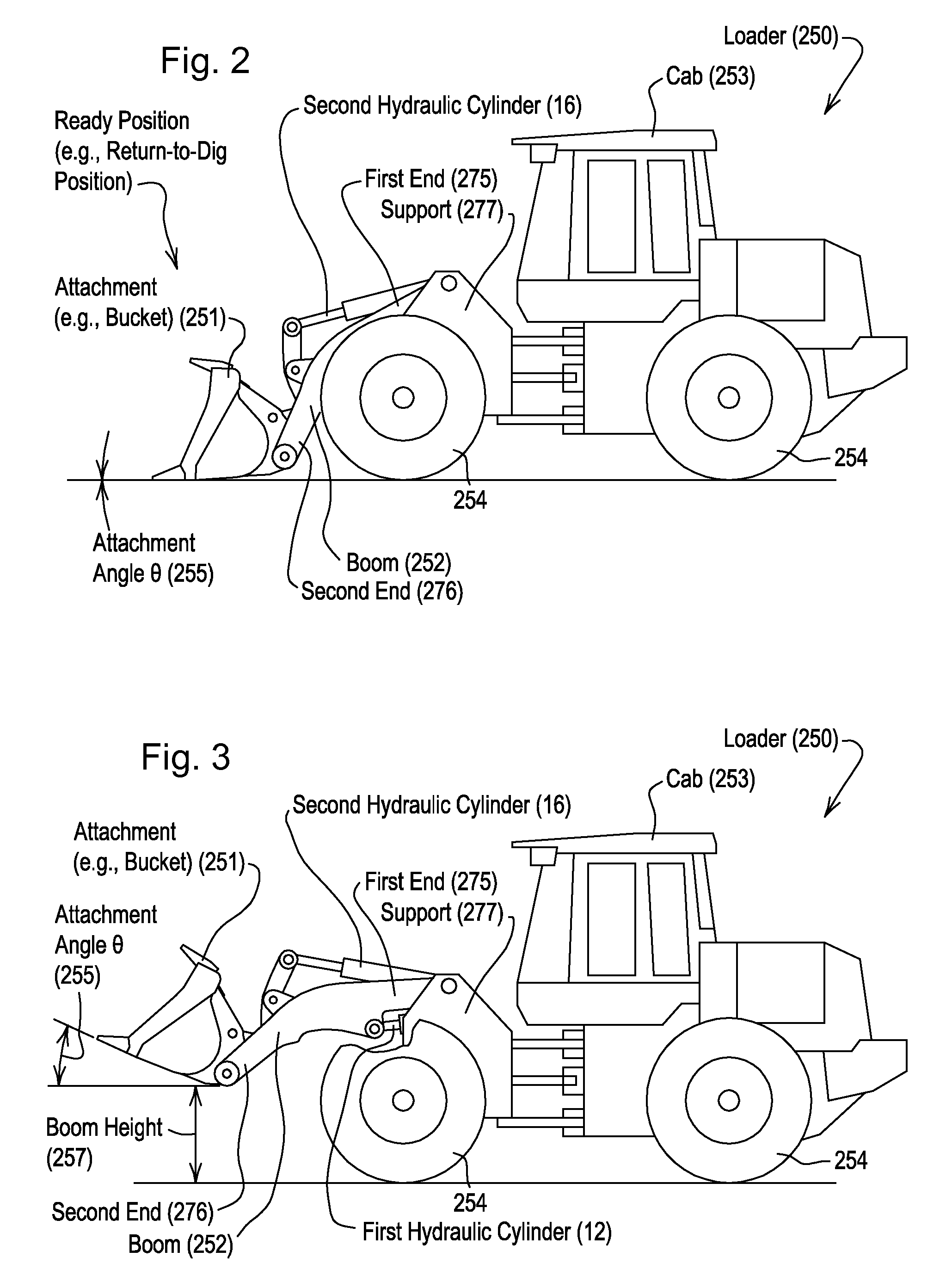
[0052]In step S400, a user interface 22 establishes a ready position associated with at least one of a target boom position and a target attachment position. The target boom position may be associated with a target boom height that is greater than a minimum boom height or ground level. The target attachment position is associated with an attachment angle greater than a minimum angle or zero degrees (e.g., a level bucket where a bottom is generally horizontal).

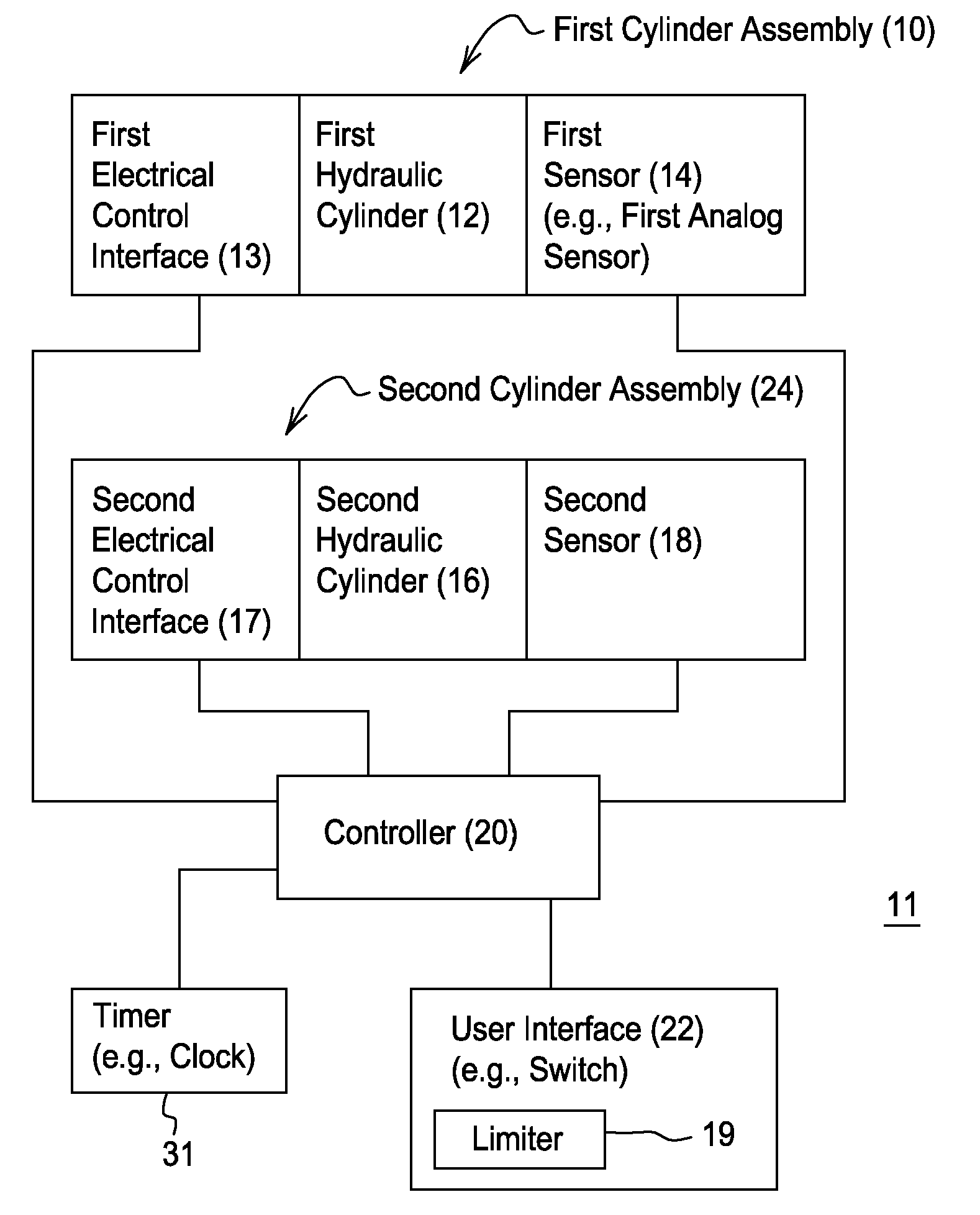
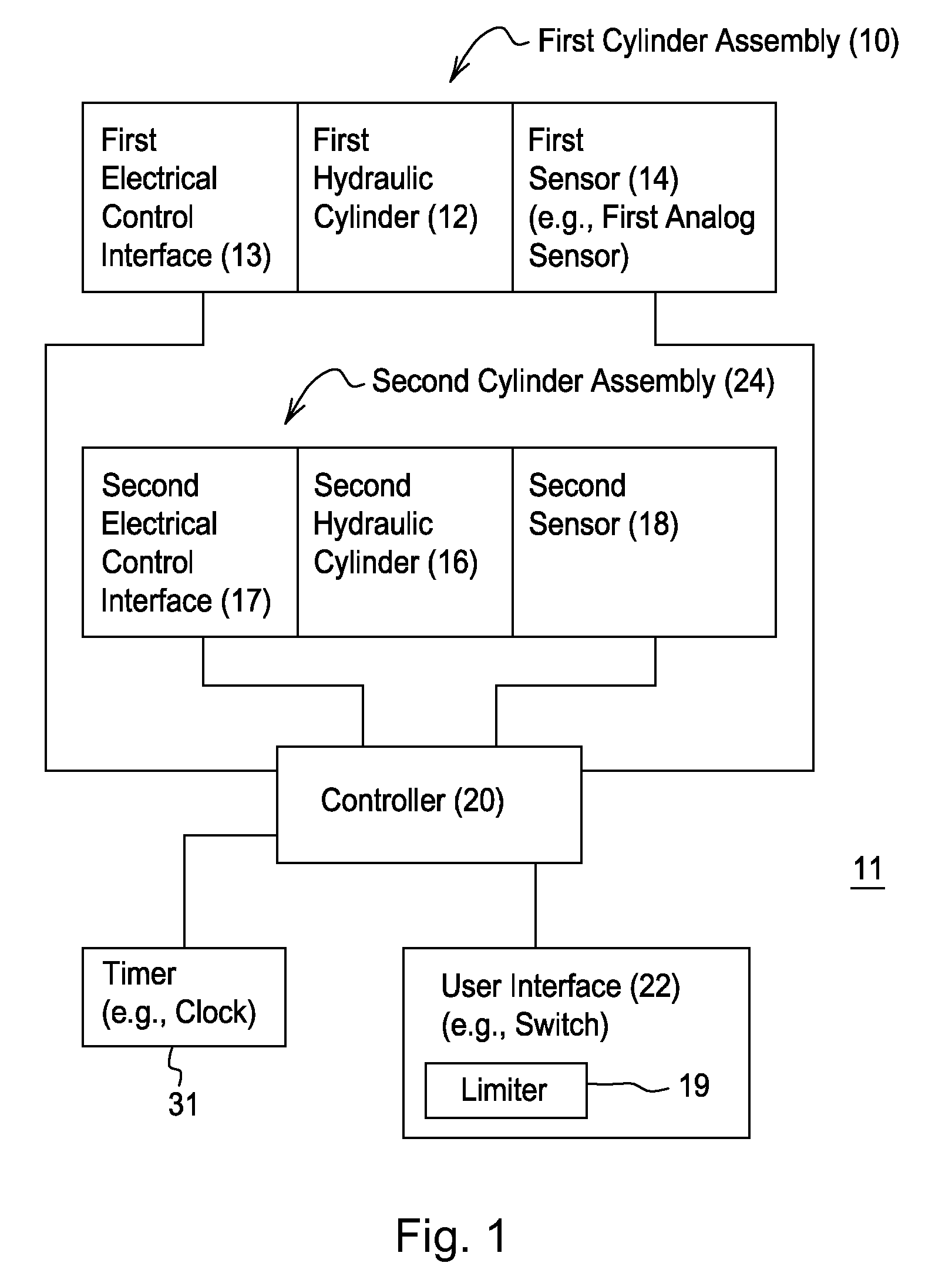
[0053]In step S402, a first sensor 14 detects a boom position of the boom 252 based on a first linear position of a first movable member associated with first hydraulic cylinder 12. The first movable member may comprise a piston, a rod, or another member of the first hydraulic cylinder 12, or a member of a sensor that is mechanically coupled to the piston, the rod, or the first hydraulic cylinder 12...


PUM


Abstract

A first sensor detects a boom angle of a boom with respect to a support. An attachment is coupled to the boom. A second cylinder is associated with the attachment. A second sensor detects an attachment angle of the attachment with respect to the boom. An accelerometer detects an acceleration or deceleration of the boom. A switch accepts a command to enter a ready position state from another position state. A controller controls the first hydraulic cylinder to attain a boom angle within the target boom angular range and for controlling the second cylinder to attain an attachment angle within the target attachment angular range associated with the ready position state in response to the command in conformity with at least one of a desired boom motion curve and a desired attachment motion curve.

Description

[0001]This document (including the drawings) claims priority based on U.S. provisional application No. 60 / 890,927, filed on Feb. 21, 2007 and entitled AUTOMATED CONTROL OF BOOM AND ATTACHMENT FOR WORK VEHICLE, under 35 U.S.C. 119(e).FIELD OF THE INVENTION[0002]This invention relates to an automated control of a boom and attachment for a work vehicle.BACKGROUND OF THE INVENTION[0003]A work vehicle may be equipped for a boom and attachment attached to the boom. A work task may require repetitive or cyclical motion of the boom or the attachment. Where limit switches or two-state position sensors are used to control the motion of the boom or attachment, the work vehicle may produce abrupt or jerky movements in automated positioning of the boom or attachment. The abrupt or jerky movements produce unwanted vibrations and shock that tend to reduce the longevity of hydraulic cylinders and other components. Further, the abrupt or jerky movements may annoy an operator of the equipment. Accord...

Claims


Application Information

Patent Timeline
Patent Type & Authority Applications(United States)
IPC IPC(8): G01M17/00
CPCE02F3/847
Inventor SAHLIN, MARK PETERMEREDITH, JASONSAMUELSON, JERRY ANTHONYJOHNSON, DAVID AUGUSTANDERSON, ERIC RICHARD
Owner DEERE & CO
Why Eureka
Try Eureka