Strapping system

Active Publication Date: 2008-08-28
VELCRO IP HLDG LLC
View PDF10 Cites 30 Cited by
  • Summary
  • Abstract
  • Description
  • Claims
  • Application Information

AI Technical Summary

Problems solved by technology

Once touch fastened, the arrays may create a releasable closure that has relatively strong resistance to shear forces to keep the it

Method used


Image

  • Strapping system
  • Strapping system
  • Strapping system

Examples


Embodiment Construction

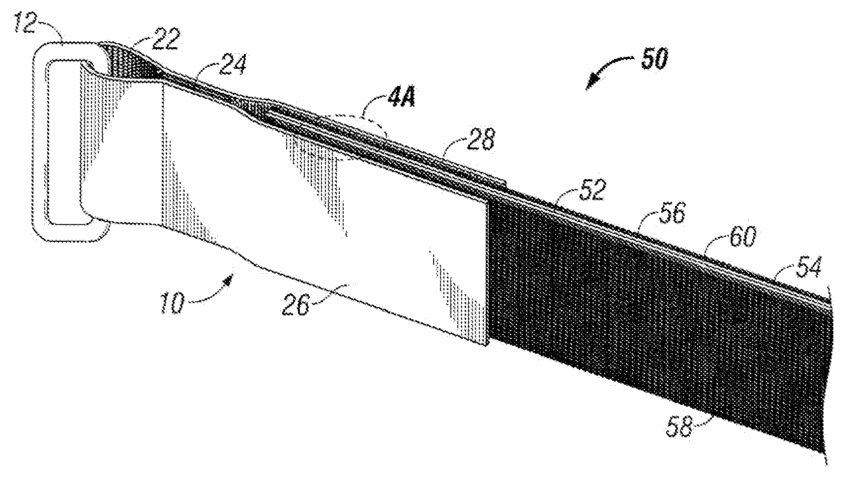
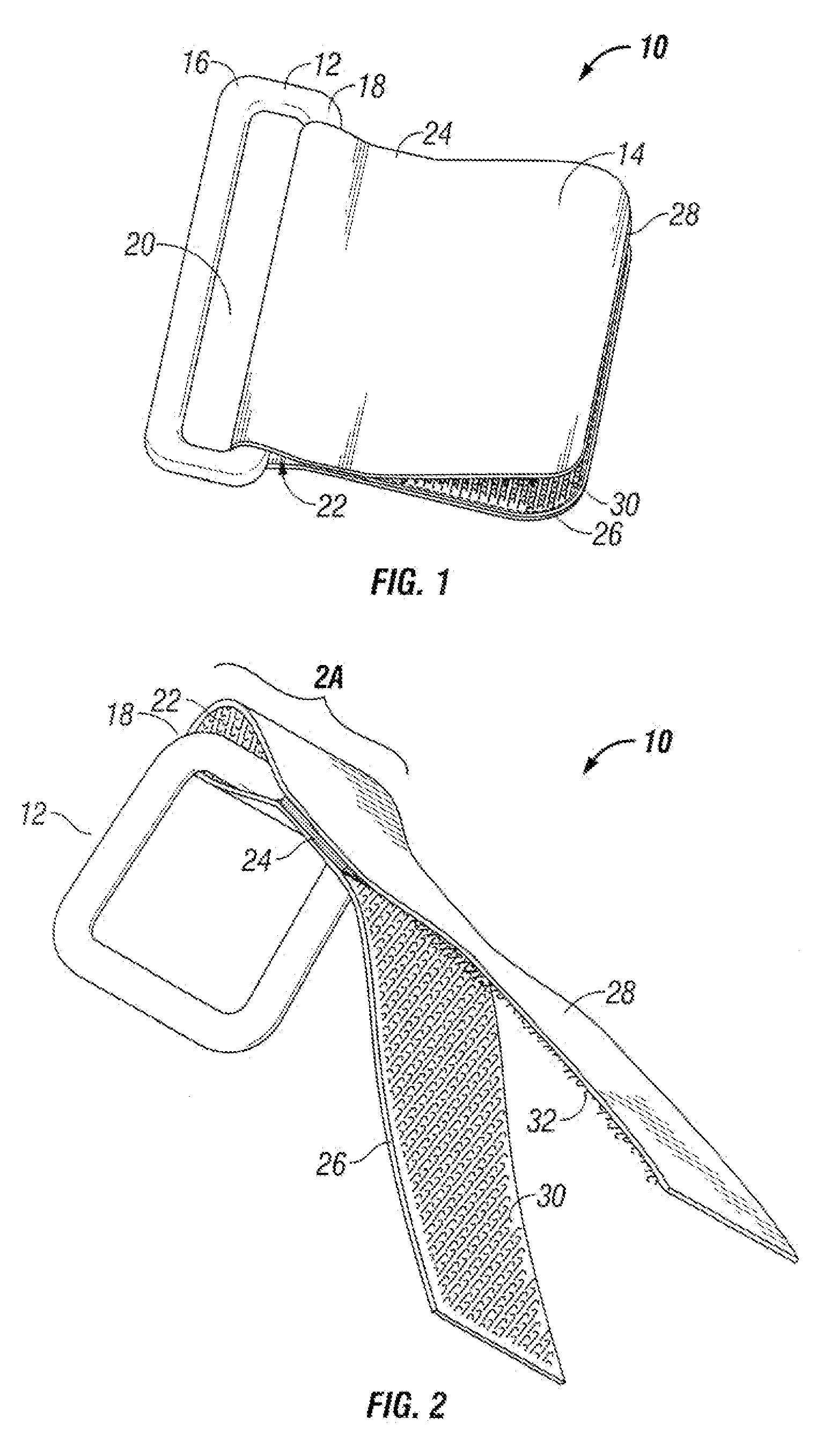
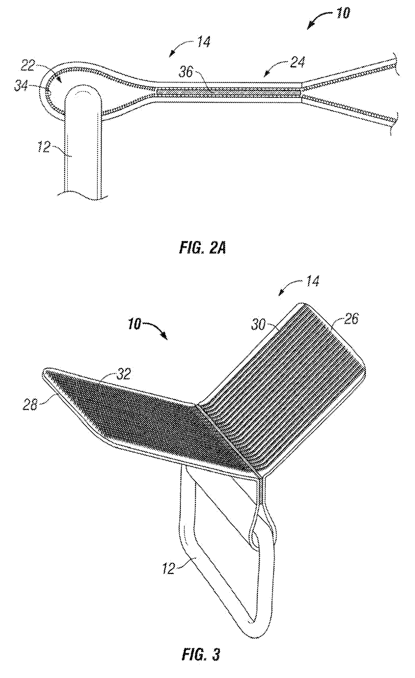
[0026]With reference to FIG. 1, a top view of a buckle assembly 10 in accordance with one embodiment is illustrated. The buckle assembly 10 includes a buckle 12 and an attachment portion 14. The buckle 12 may be any form of rectangular or curved rim or fitment that when attached to one of a strap is able to fasten that end to another part of the strap or a different strap. The buckle 12 may alternatively be configured to couple to another interlocking buckle at another part of the strap (see FIG. 12, for example). In the configuration illustrated in FIG. 1, the buckle 12 has a first leg 16 and a second leg 18 that define an opening 20, which is sized to receive the strap, as will be described further below. The buckle 12 may be formed, cast, or otherwise constructed from any suitably rigid material. For example, the buckle 12 may comprise plastic, metal, wood, or a composite material.

[0027]The attachment portion 14 may be composed of any material capable of holding or forming touch ...


PUM


Abstract

A strapping system including a strap having opposite first and second faces carrying first and second arrays of touch fastening elements respectively and a buckle assembly releasably attached to one end of the strap and defining an opening sized to receive an opposite end of the strap. The buckle assembly includes a buckle and an attachment portion coupled to the buckle, the attachment portion having opposing surfaces that releasably engage the touch fastening elements on the first and second faces of the strap, respectively, to releasably secure the buckle to the strap, wherein the strap includes touch fastening elements engageable with other touch fastening elements of the strapping system when the buckle assembly attached to the strap to secure the strapping system about an object.

Description

TECHNICAL FIELD[0001]This invention relates to strapping systems and methods of their use and manufacture.BACKGROUND[0002]There are many commercial, industrial, and residential applications that involve securing or bundling items together with straps. For example, in the automotive or telecommunication industries, wires or wiring harnesses are often bundled together using straps. Similarly, in the transportation industry, straps are used to bundle goods together or to secure goods to pallets. These straps are typically releasably secured to enable the bundles to be separated later if needed (e.g., for distribution, for repair, etc.).[0003]One type of strap is known as a touch fastening strap. Touch fastening straps typically have an array of touch fastening elements on one portion of a fabric or resin strap and an array of touch fastening element on another portion of the strap. The strap is then looped around the items to be bundled and the two touch fastening arrays are coupled to...

Claims


Application Information

Patent Timeline
IPC IPC(8): A44B18/00
CPCB65D63/10F16L3/137Y10T24/47Y10T24/2708Y10T24/4764F16L3/233
Inventor OBIOLS, JOSEPROVIRA, GEMMA
Owner VELCRO IP HLDG LLC
Why Eureka
Try Eureka