Folding knife

Active Publication Date: 2008-08-28
GBII DBA COLUMBIA RIVER KNIFE & TOOL
View PDF16 Cites 62 Cited by
  • Summary
  • Abstract
  • Description
  • Claims
  • Application Information

AI Technical Summary

Benefits of technology

[0012]Additionally, the safety mechanism can further comprise a base portion having a shoulder portion and a lever portion extending therefrom. The lever portion can have a manually operable exposed member and the shoulder portion can be configured suc...

Problems solved by technology

When pivoting the blade to the open position, however, the motion limiting member moves...

Method used


Image

  • Folding knife
  • Folding knife
  • Folding knife

Examples


Embodiment Construction

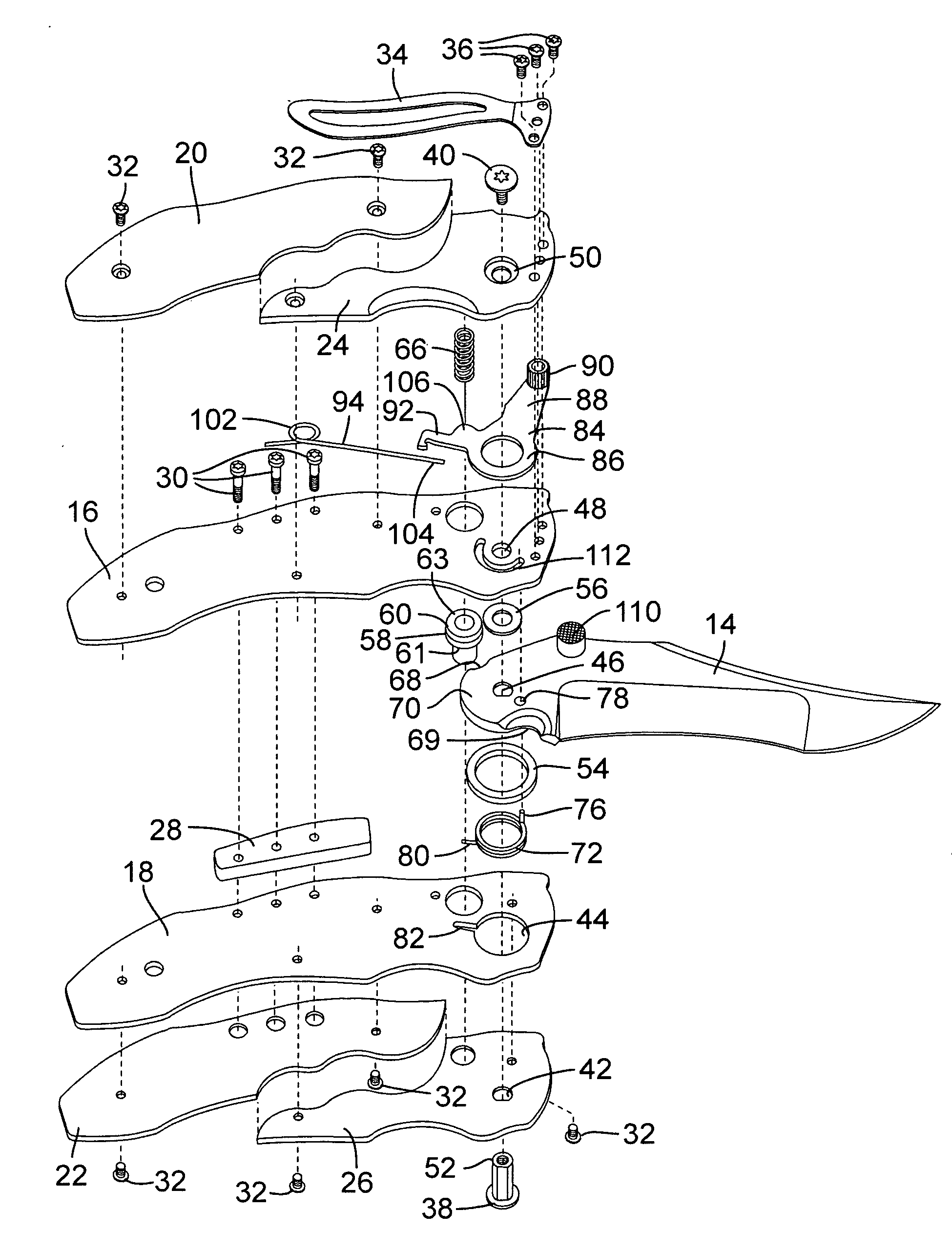
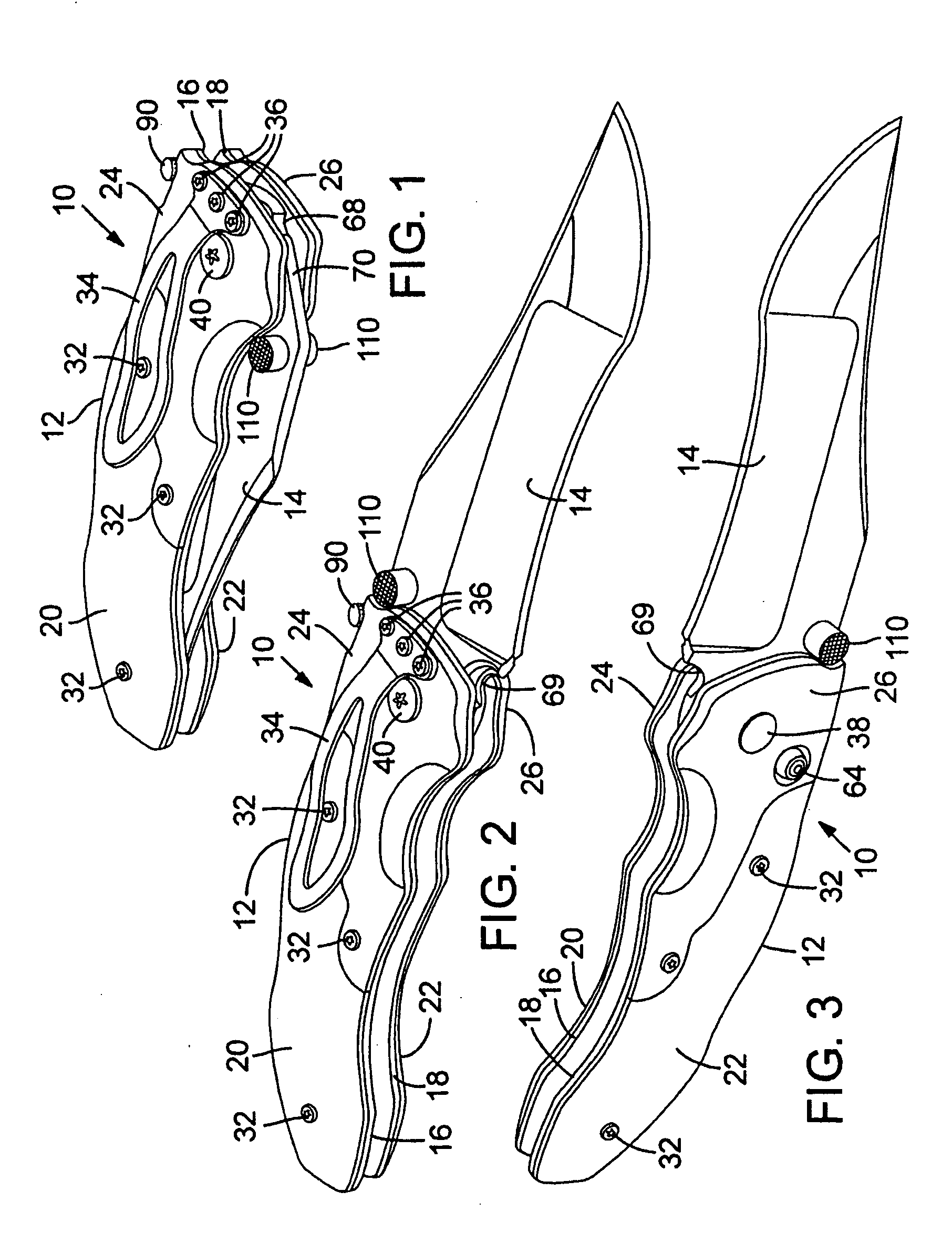
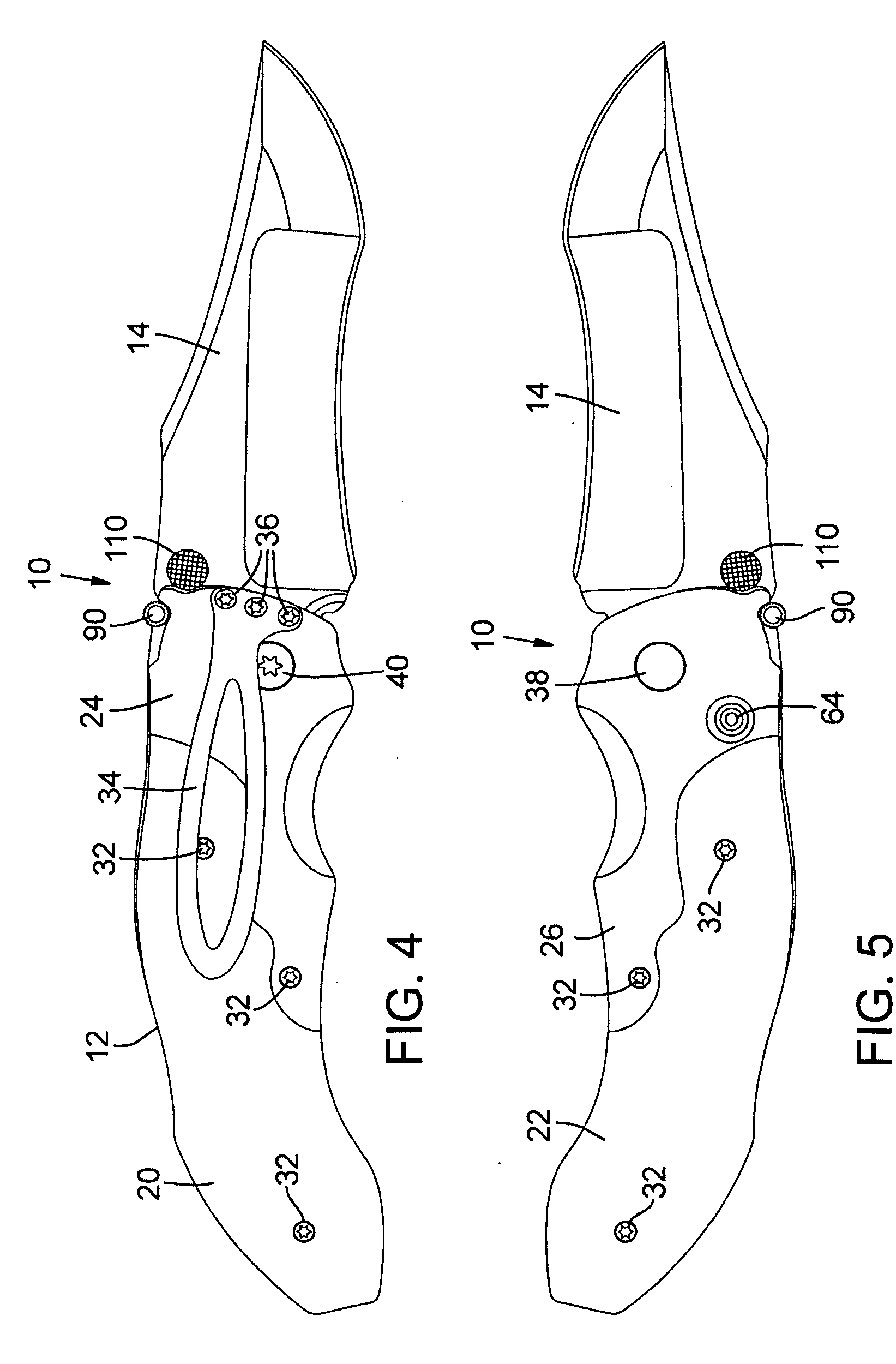
[0037]FIGS. 1-8 show an automatic folding knife 10, according to one embodiment, comprising a handle portion, or handle, 12, and a blade 14 pivotably connected to the handle portion 12. The blade 14 can be pivoted between an open position extending from the handle portion for use (FIGS. 2-7) and a closed, or folded, position at least partially received in the handle portion (FIG. 1).

[0038]As best shown in FIG. 8, the handle portion 12 in the illustrated embodiment comprises first and second inner plates, or liners, 16 and 18, respectively, first and second outer plates 20 and 22, respectively, mounted to the outside surfaces of the inner plates 16, 18, and first and second bolsters 24 and 26, respectively, mounted to the outside surfaces of the inner plates 16, 18 adjacent the blade 14. A spacer / spine portion 28 is positioned between the inner plates 16, 18 along the top edge of the handle portion. The inner plates 16, 18 can be secured to each other and the spacer 28 by screws 30 e...


PUM


Abstract

A folding knife in exemplary embodimentsTong comprises a handle portion, a blade, a locking cross-bolt, and a motion limiting member coupled to the handle. When the blade is in the closed position, the motion limiting member is in a first position that prevents the cross-bolt from moving to its locked position. When pivoting the blade to the open position, the motion limiting member moves to a second position that does not prevent the cross-bolt from moving to its locked position. A biased safety mechanism can also be used to block the cross-bolt from moving to an unlocked position.

Description

CROSS REFERENCE TO RELATED APPLICATION[0001]This application claims the benefit of U.S. Provisional Patent Application Ser. No. 60 / 901,527 filed Feb. 14, 2007.BACKGROUND[0002]The present disclosure concerns embodiments of a folding knife.Description of the Related Art[0003]A folding knife is a knife with a blade that pivots about a point, thereby allowing the blade to fold into the handle. Folding knives can be either manual or automatic. A manual folding knife typically has a thumb stud or other grasping mechanism to permit the user to easily move the blade from a closed position to an open position. On the other hand, automatic knives use some type of stored energy to force the blade into an open position upon release of the stored energy. Folding knives, both manual and automatic, can also include a mechanism to hold the blade in an open position. For example, some folding knives have a slip joint that hold the blade in the open position until a certain amount of pressure is appl...

Claims


Application Information

Patent Timeline
IPC IPC(8): B26B1/04
CPCB26B1/046
Inventor BREMER, RODNEY L.FLAGG, DOUGLAS B.CHIU, TONG
Owner GBII DBA COLUMBIA RIVER KNIFE & TOOL
Why Eureka
Try Eureka