Daylighting system comprising light re-direction elements in a Venetian blind

a daylighting system and venetian blind technology, applied in the direction of optics, light protection screens, door/window protective devices, etc., can solve the problems of compromising the ability of venetian blinds to redirect natural light into the deep interior of buildings, unable to teach the use of familiar and commonly available venetian blinds, and none of the prior art systems are suited to conversion of standard venetian blinds

Inactive Publication Date: 2008-08-28
EDMONDS IAN ROBERT
View PDF14 Cites 30 Cited by
  • Summary
  • Abstract
  • Description
  • Claims
  • Application Information

AI Technical Summary

Benefits of technology

[0005]The daylighting system of this invention comprises one or more light redirecting elements inserted between the slats of a conventional Venetian blind. The slats of the Venetian blind are tilted so that a light redirecting element can be supported gravitationally between a slat and the outer support strings of the Venetian blind. Each light redirecting element is a strip of reflective material formed into an angle section. The upper arm of the angle section reflects sunlight u

Problems solved by technology

However, tilting a Venetian blind to block radiant input compromises the ability of the Venetian blind to redirect natural light into the deep interior of buildings.
In particular none of the prior art teaches the use of the familiar and commonly available Venetian blind as an integral part of a daylighting system.
Further the louver elements outlined in the prior art are complex in sh

Method used


Image

  • Daylighting system comprising light re-direction elements in a Venetian blind
  • Daylighting system comprising light re-direction elements in a Venetian blind
  • Daylighting system comprising light re-direction elements in a Venetian blind

Examples


second embodiment

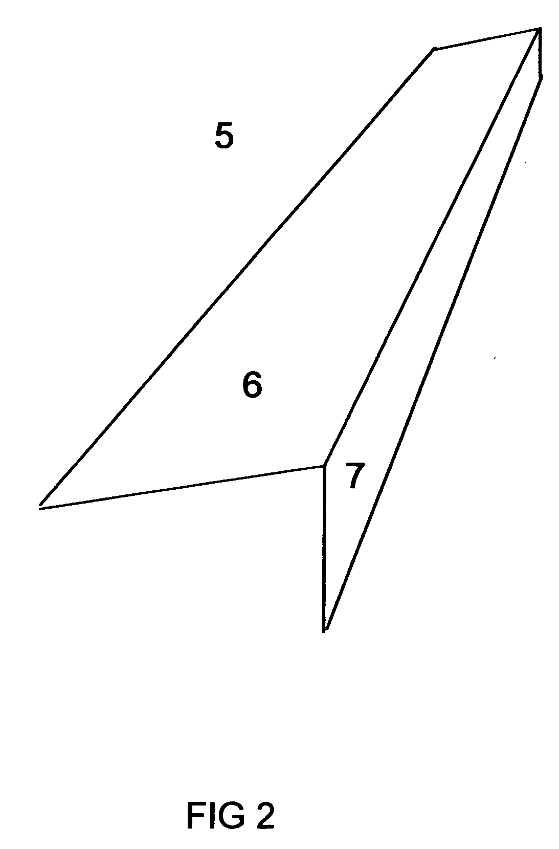
[0014]In the invention the diffusion of reflected light from the surface of arm 6 is achieved by forming the arm 6 with a slight upward convex curvature prior to or after folding into an angle section.

third embodiment

[0015]In a third embodiment the diffusion of reflected light from the surface of arm 6 is achieved by a fine general roughening of the metal forming the surface of arm 6 or by painting the surface of arm 6 with a high gloss white paint.

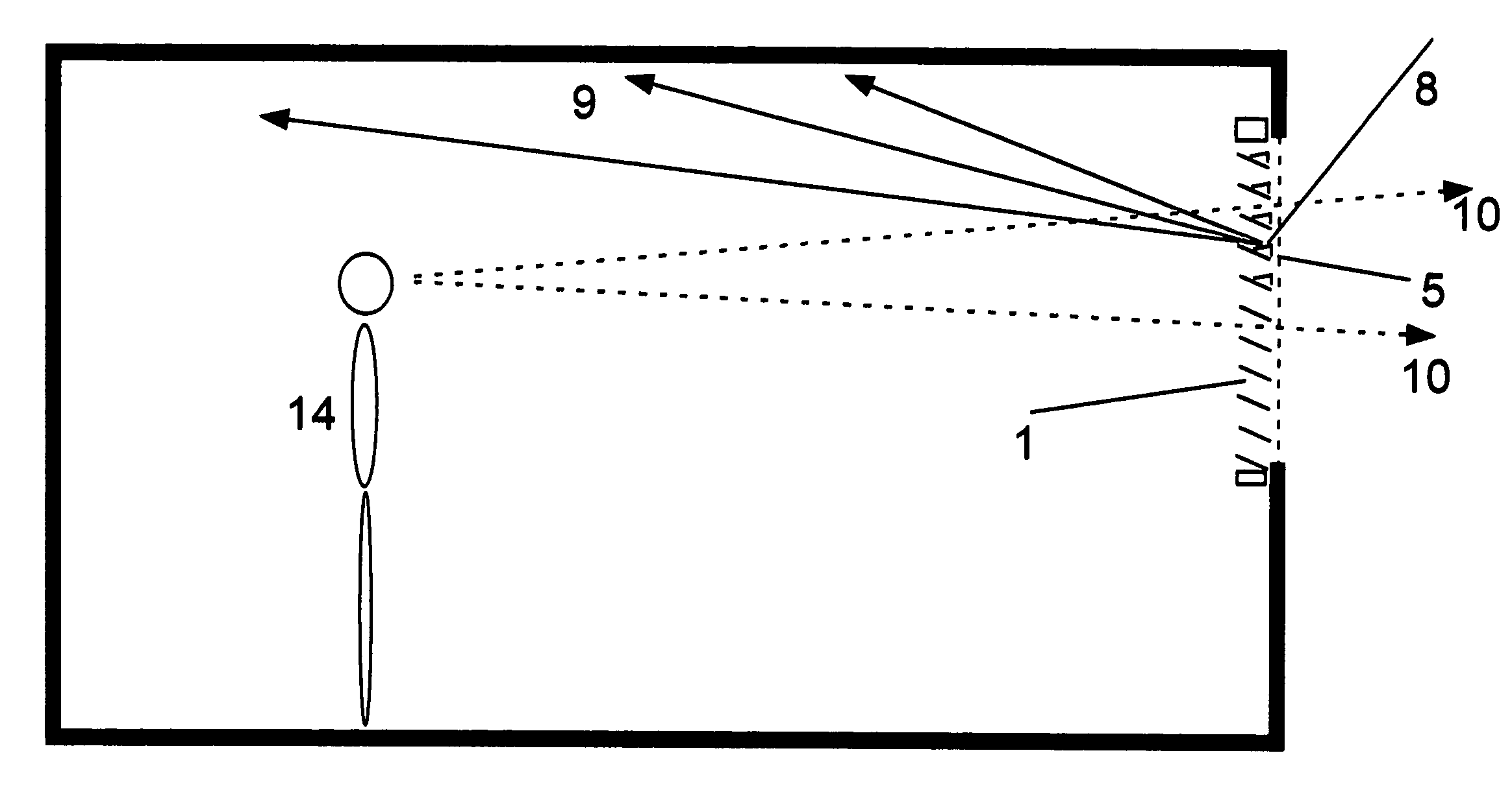
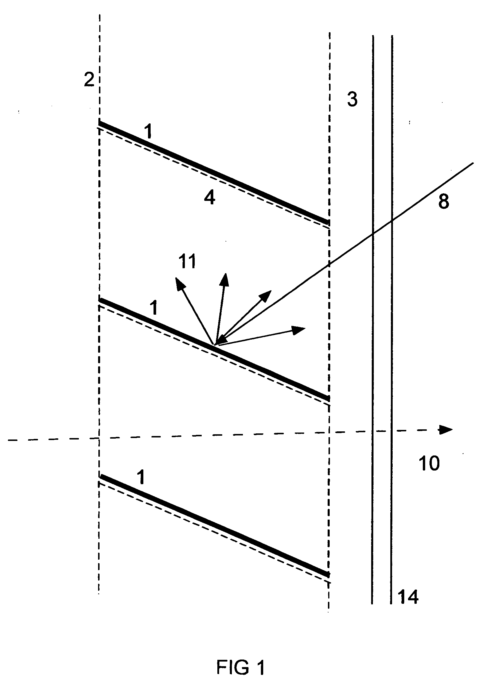
[0016]The purpose of diffusely reflecting sunlight from upper arm 6 of the light redirecting elements 5 is to spread the sunlight reflected from each light redirecting element over a wide extent of the ceiling of the room being illuminated. This desired effect is illustrated in FIG. 5 which shows the daylighting system of this invention installed in the window of a room. As indicated in FIG. 5 light redirecting elements 5 are inserted between the slats in the upper half of the Venetian blind. The reason for insertion only in the upper half of the blind is explained below. Typically, incident sunlight 8 is diffusely reflected from upper arm 6 of each of the elements into an output 9 that is spread over a wide extent of the ceiling of the room. As the d...


PUM


Abstract

A daylighting system comprising one or more light redirecting elements and a horizontal slat Venetian blind. The light redirecting elements are inserted between the slats of the Venetian blind and are supported between the slats and the outer strings of the Venetian blind. Each light redirecting element is a thin strip of reflective material formed into an angle section. The upper arm of the angle section reflects sunlight upwards through the Venetian blind and deeply into the interior of the building. The side arm of the angle section reflects sunlight back out of the window. The reflecting surface of an upper arm of a light redirecting element is treated to reflect light diffusely into a narrow angular range. The reflecting surface of a side arm of a light redirecting element is treated to reflect light diffusely into a wide angular range. The daylighting system is installed in the window of a building to redirect sunlight on to the ceiling of the building to improve natural illumination in the building.

Description

FIELD OF THE INVENTION[0001]This invention when installed in a window redirects sunlight over the ceiling of a building to improve natural illumination in the deep interior of the building.BACKGROUND[0002]In sunny climates the radiant heat through windows must be controlled to avoid excessive heating of buildings and excessive cooling loads. A horizontal louver is an effective means of controlling the input of radiant heat through a window. The common name for a variable tilt horizontal louver slat blind is louver blind or Venetian blind. The Venetian blind is one of the most commonly used and inexpensive means for controlling radiant heat gain through windows. However, tilting a Venetian blind to block radiant input compromises the ability of the Venetian blind to redirect natural light into the deep interior of buildings. The reason for this is illustrated in the section view of a Venetian blind, FIG. 1. A typical Venetian blind comprises an array of opaque slats 1 supported by st...

Claims


Application Information

Patent Timeline
IPC IPC(8): E06B9/386
CPCE06B2009/2417E06B9/386
Inventor EDMONDS, IAN ROBERT
Owner EDMONDS IAN ROBERT
Why Eureka
Try Eureka