Lamp with adjustable color

a technology of adjustable color and lamp, which is applied in the direction of discharge tube/lamp details, discharge tube luminescnet screens, electric discharge lamps, etc., can solve the problems of complex control mechanism, need for a microprocessor, and easy error

Active Publication Date: 2008-12-04
GLOBAL OLED TECH
View PDF5 Cites 104 Cited by
  • Summary
  • Abstract
  • Description
  • Claims
  • Application Information

AI Technical Summary

Benefits of technology

[0014]A white-light electro-luminescent lamp has an adjustable spectral power distribution, including a first light-emitting element that emits light within each of three wavelength bands, 1) between 440 and 520 nm, 2) between 520 and 600 nm, and 3) between 600 and 680 nm. An integrated spectral power within the first wavelength band is higher than the second wavelength band and the integrated spectral power within the second wavelength band is higher than the third wavelength band. A second light-emitting element emits light within each of three wavelength bands, 1) between 440 and 520 nm, 2) between 520 and 600 nm, and 3) between 600 and 680 nm. The integrated spect

Problems solved by technology

This control mechanism can be complex and is prone to error as each of the lamps age.
However, the authors fail to address the issue that by having three independent light sources, the chromaticity coordinates of the light that will be generated is likely to fall within a two-dimensional triangle in CIE chromaticity space with each corner of the triangle being represented by the chromaticity coordinate of each of the light sources.
The need for a microprocessor can add significant cost and complexity to the overall system design.
Unfortunately, this embodiment requires that either the blue or yellow LED be employed with the white LED.
Therefore, if the system is not calibrated properly or if one of the LEDs ages at a different rate than another, it is likely that a luminance shift will occur at the point where one LED is turned off and the other is turned on.
This has the potential to create a discontinuous change in color temperature as well as a sudden perceptual change in the perceived brightness of the lamp.
Once again, the presence of three (e.g., red, green and blue), independently-addressable light-emitting elements within the lamp to allow the lamp to produce light having a

Method used


Image

  • Lamp with adjustable color
  • Lamp with adjustable color
  • Lamp with adjustable color

Examples


Embodiment Construction

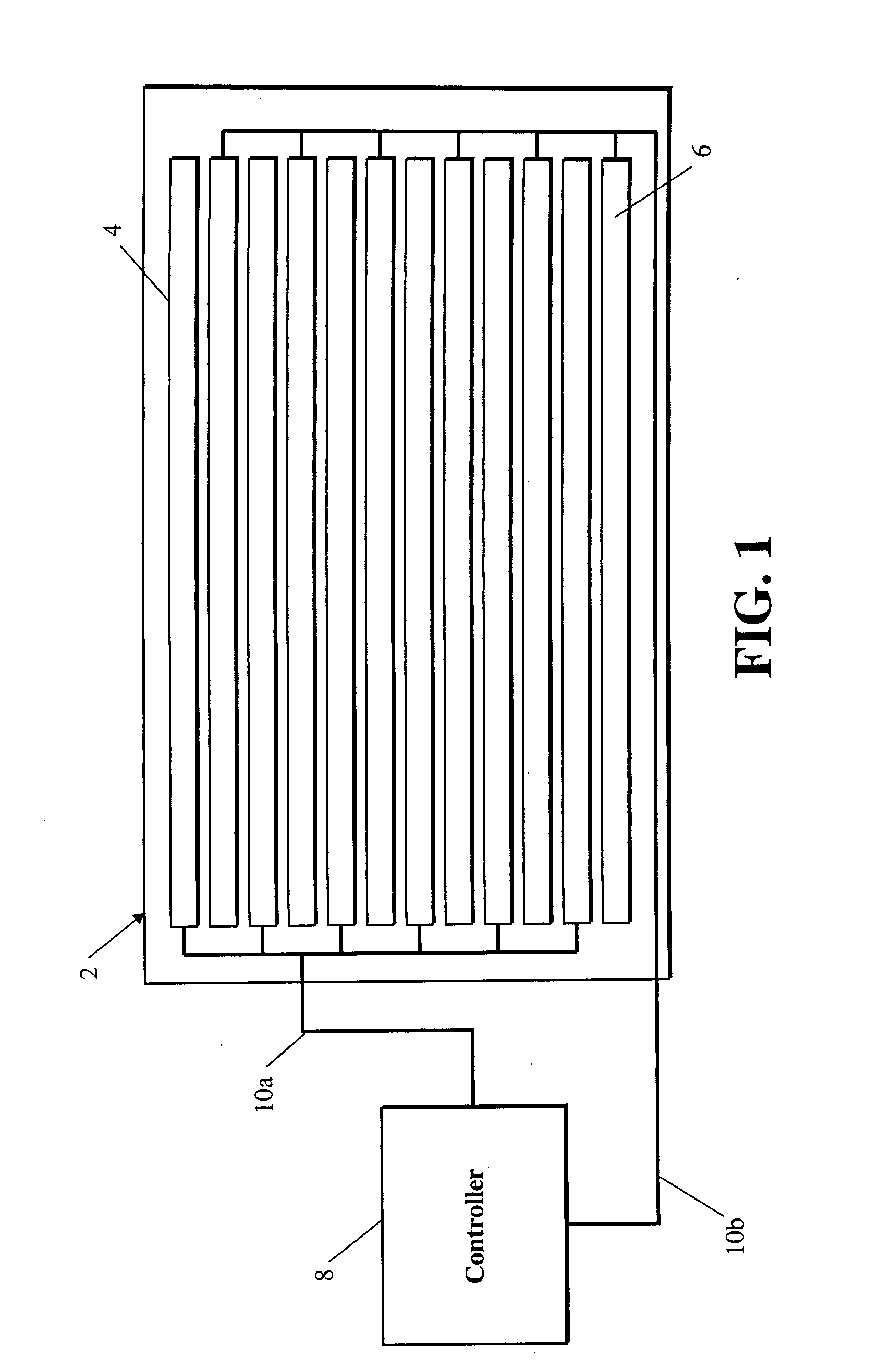
[0030]The present invention provides a white-light, electro-luminescent lamp 2 as shown in FIG. 1, having an adjustable spectral power distribution emission, wherein the spectral power distribution approximates the spectral power distribution of a plurality of standard daylight distributions as specified by the CIE. This lamp 2 includes two light-emitting elements 4, 6. The first light-emitting element 4 emits light within each of three wavelength bands, including a first wavelength band between 440 and 520 nm, a second wavelength band between 520 and 600 nm, and a third wavelength band between 600 and 680 nm; wherein an integrated spectral power within the first wavelength band is higher than the second wavelength band, and the integrated spectral power within the second wavelength band is higher than the third wavelength band. The second light-emitting element 6 emits light within each of three wavelength bands, including a first wavelength band between 440 and 520 nm, a second wa...


PUM


Abstract

A white-light electro-luminescent lamp having an adjustable spectral power distribution, including a first light-emitting element which emits light within each of three wavelength bands, 1) between 440 and 520 nm, 2) between 520 and 600 nm, and 3) between 600 and 680 nm. A second light-emitting element emits light within each of three wavelength bands, 1) between 440 and 520 nm, 2) between 520 and 600 nm, and 3) between 600 and 680 nm. A controller modulates the integrated spectral power of the light produced by the first and the second light-emitting elements such that the spectral power distribution of the light formed by combining the light produced by the modulated first and second light-emitting elements is substantially equal to a CIE standard daylight spectral power distribution for correlated color temperatures between 4000K-9500K.

Description

FIELD OF THE INVENTION[0001]The present invention relates to the structure and manufacture of a lamp and, more particularly, to a lamp capable of producing a multiplicity of colors and spectral power distributions of white light which approximate blackbody or daylight lighting sources with two, independently addressable, light-emitting elements.BACKGROUND OF THE INVENTION[0002]Lamps capable of producing multiple colors of light are known to satisfy many applications; including lamps for general purpose lighting that allow “white” light to be generated in such a way to allow the user to adjust the correlated color temperature of the light. Lights with adjustable color temperature are further known for use in specialized lighting applications, such as camera strobes and motion picture lighting systems. Within this application space, it is most desirable to create lamps that provide outputs having both colorimetric coordinates and spectral power distributions that match those of typica...

Claims


Application Information

Patent Timeline
IPC IPC(8): H01J1/62H05B37/00H05B44/00
CPCH05B33/0812H05B33/0821H05B33/0863H05B33/0869Y02B20/343H05B45/22H05B45/395H05B45/40H05B45/20Y02B20/30
Inventor MILLER, MICHAEL E.MADDEN, THOMAS E.COK, RONALD S.KANE, PAUL J.
Owner GLOBAL OLED TECH
Why Eureka
Try Eureka