Materials handling vehicle having at least one controller coupled to a front wall of a frame
a technology of a front wall and a controller, applied in the direction of transportation and packaging, electric propulsion mounting, tractors, etc., can solve the problem of limited size of the operator compartmen
- Summary
- Abstract
- Description
- Claims
- Application Information
AI Technical Summary
Benefits of technology
Problems solved by technology
Method used
Image

Examples
first embodiment
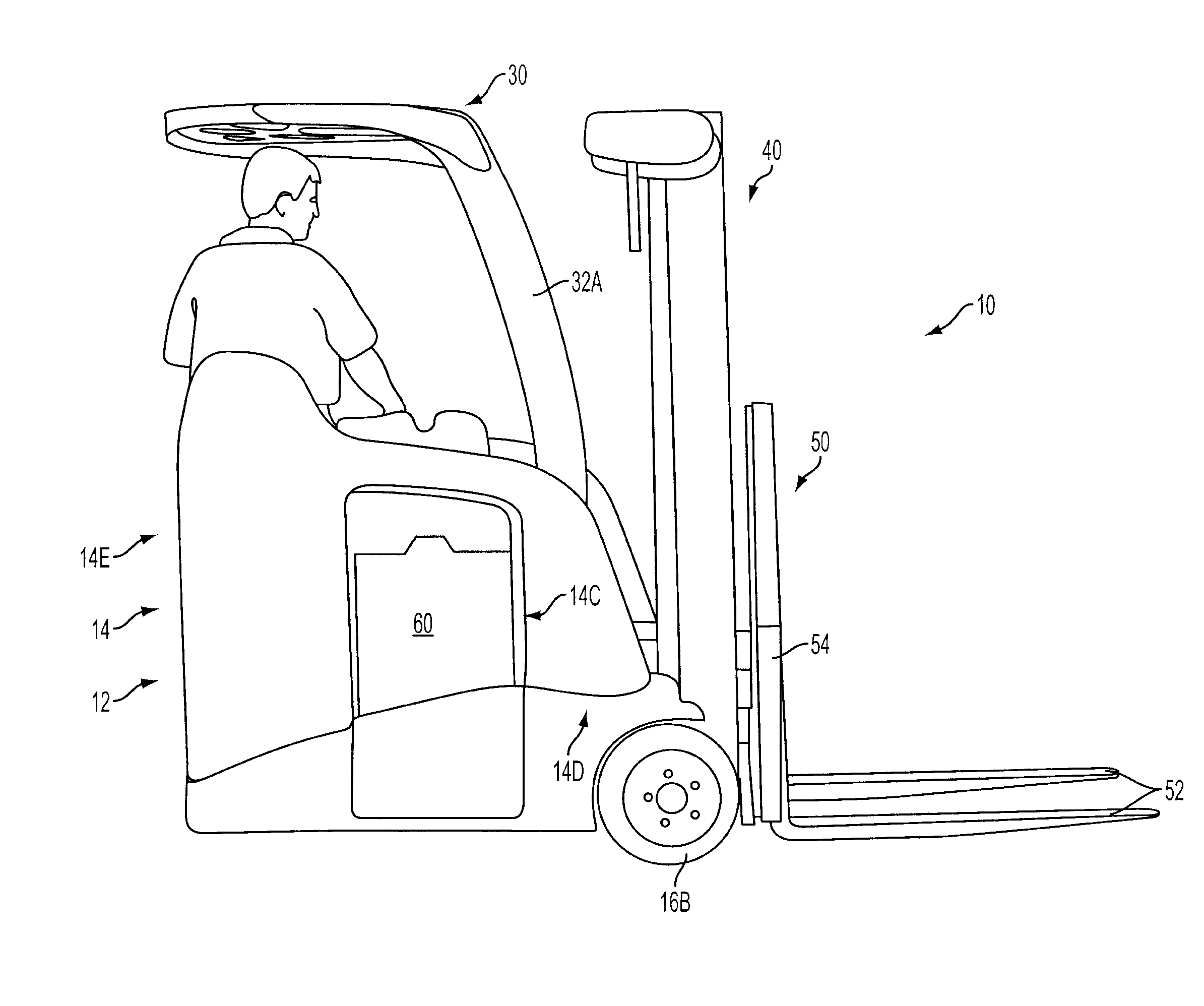
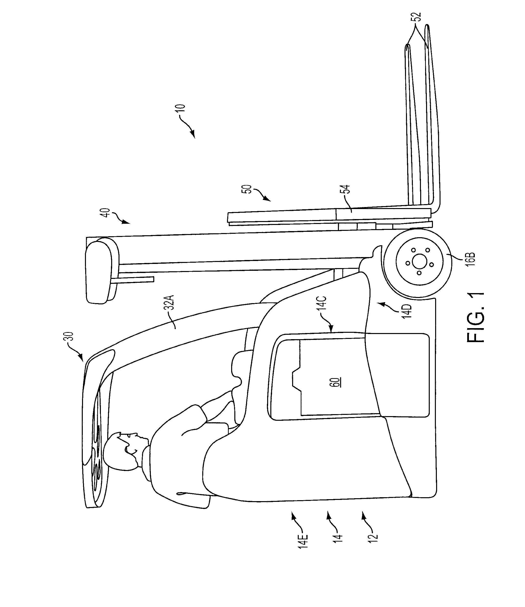
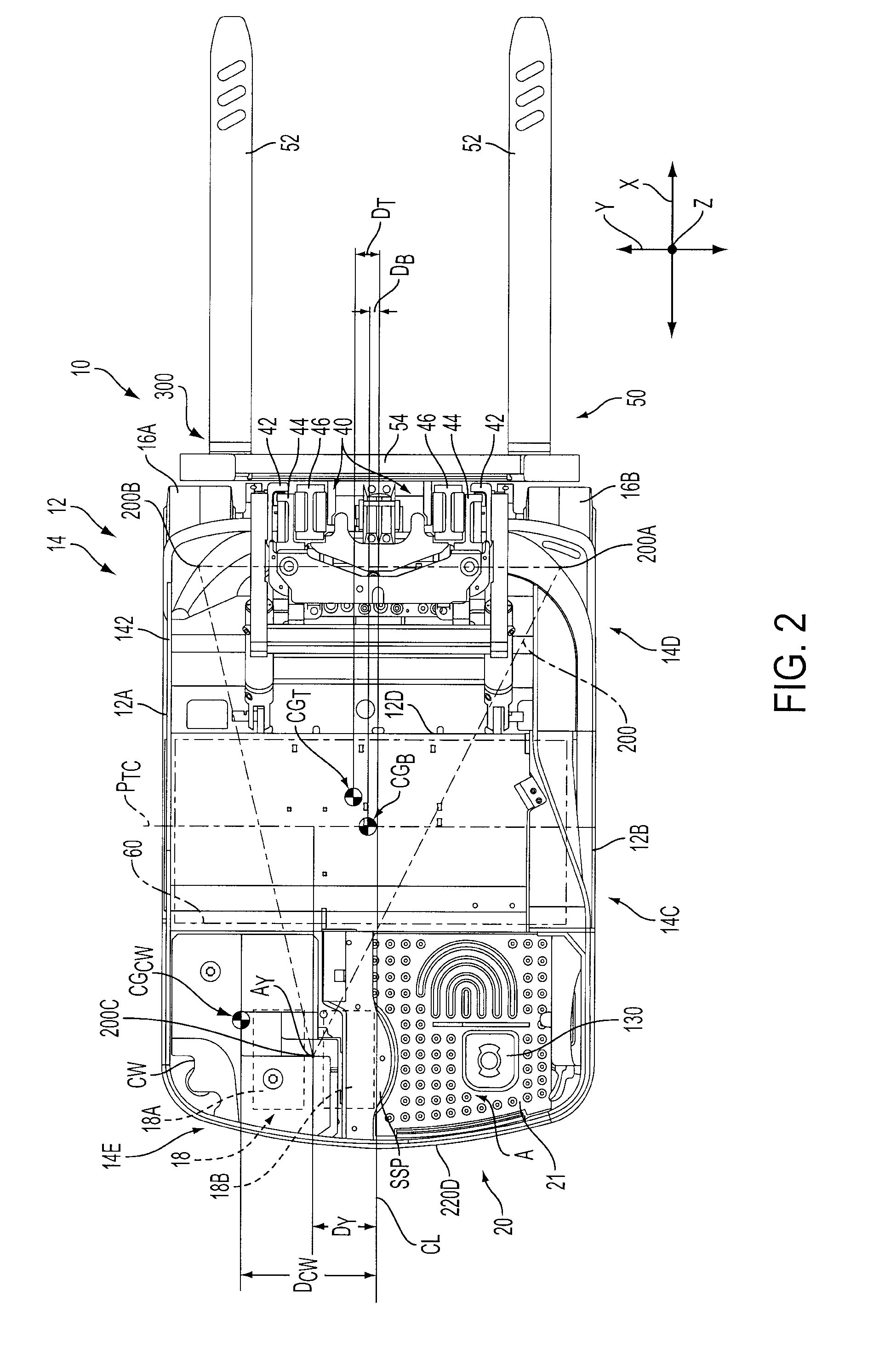
[0033]Reference is now made to FIGS. 1-4, which illustrate the stand-up counterbalanced fork lift truck 10 constructed in accordance with the present invention. The fork lift truck 10 comprises a frame 12 including a main body 14. The main body 14 includes a battery compartment 14C for housing a battery 60 (the battery is not illustrated in FIGS. 5-8 and 11), a front portion 14D and a rear portion 14E, see FIGS. 1 and 2. The truck 10 further comprises first and second driven wheels 16A and 16B coupled to the front portion 14D of the frame main body 14, and a rear steer wheel assembly 18 coupled to the rear portion 14E of the frame main body 14. The first and second driven wheels 16A and 16B and the rear steer wheel assembly 18 allow the truck 10 to move across a floor surface. A front wall 12D of the frame 12 defines a front wall 140C of the battery compartment 14C, see FIGS. 5 and 11.
[0034]An operator compartment 20 is located within the frame main body 14 for receiving an operator...
second embodiment
[0059]A counterbalanced fork lift truck 310 constructed in accordance with the present invention is shown in FIGS. 17-20, where like elements are referenced by like reference numerals. The truck 310 comprises a fan 1146 positioned between the controller unit 84 and a second A-pillar 332B, see FIG. 17. The second A-pillar 332B is illustrated in FIG. 17 but is not shown in FIGS. 18-20. In the embodiment illustrated in FIGS. 17-20, the A-pillar 332B is coupled to a side wall 342 of a frame 312 of the counterbalanced fork lift truck 310. The fan 1146 is mounted to a diverter bracket 1150 via bolts 1150A, see FIG. 20. A top wall 1151 of the diverter bracket 1150 is not shown in FIGS. 18 and 19. The bracket 1150 defines an internal cavity 1152 through which air moves after it passes through the fan 1146. The air then moves from the internal cavity 1152 into and through a path defined by the mounting plate 140, the frame front wall 12D, the rear walls 84B and 701 of the controller unit 84 ...
PUM
 Abstract
Description
Claims
Application Information
 - Generate Ideas
- Intellectual Property
- Life Sciences
- Materials
- Tech Scout
- Unparalleled Data Quality
- Higher Quality Content
- 60% Fewer Hallucinations
Browse by: Latest US Patents, China's latest patents, Technical Efficacy Thesaurus, Application Domain, Technology Topic, Popular Technical Reports.
© 2025 PatSnap. All rights reserved.Legal|Privacy policy|Modern Slavery Act Transparency Statement|Sitemap|About US| Contact US: help@patsnap.com