
Nozzle-based atomization system

a technology of atomization system and nozzle, which is applied in the direction of pliable tubular containers, lighting and heating apparatus, combustion types, etc., can solve the problems of increasing the drug deposition in the mouthpiece, poor the decrease of actual drug delivery to the patient, so as to reduce the velocity and impact force of the aerosol plume, reduce the aerosol plume, and reduce the effect of fine particle fraction

Inactive Publication Date: 2008-08-28
ABBOTT LAB INC
View PDF14 Cites 14 Cited by
  • Summary
  • Abstract
  • Description
  • Claims
  • Application Information

AI Technical Summary

Benefits of technology

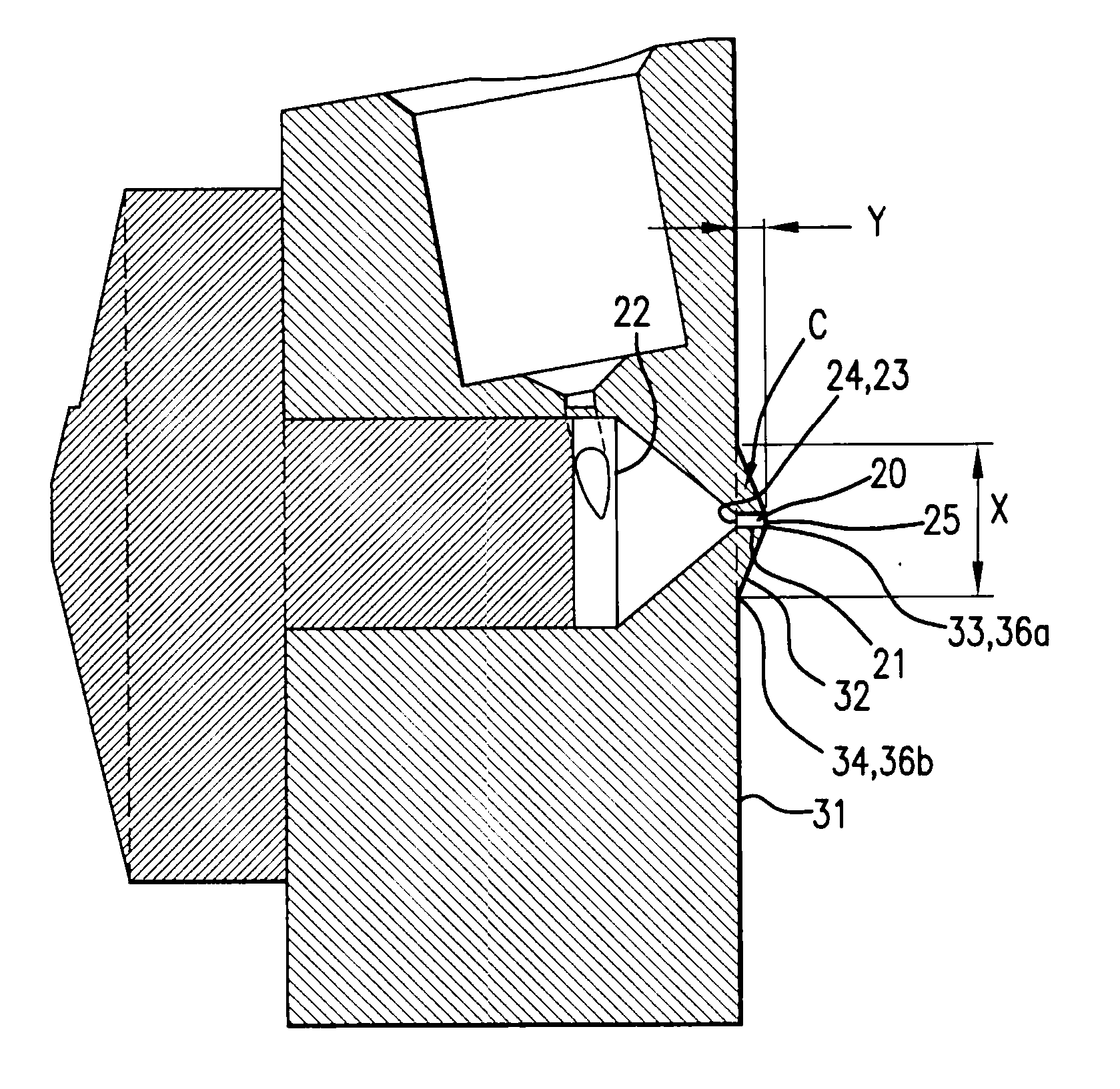
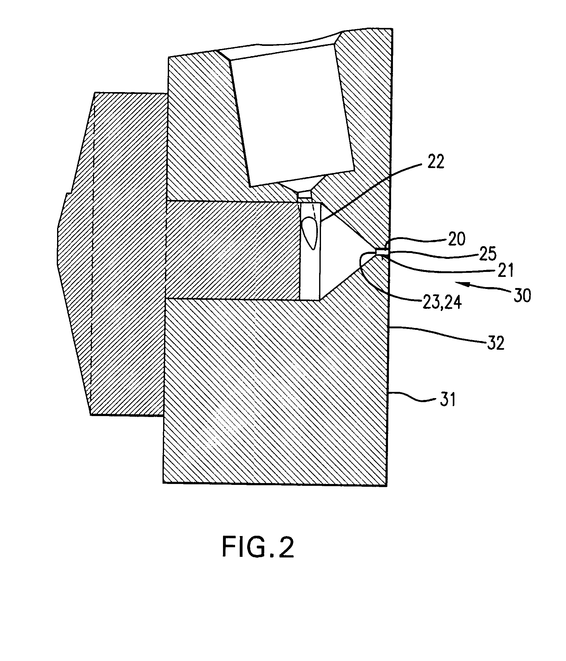
[0006]The atomization system of the present invention incorporates a vortexing nozzle with a flat or protruding exit orifice face and a diverging mouthpiece insert, which results in high fine particle fraction and modest throat deposition in conjunction with reduced aerosol plume velocity and impact force. Various embodiments of the present invention and related methods are also disclosed in the following description. The various embodiments can be used alone or in any combination, as is desired.

Problems solved by technology

Unfortunately, their commonality is accompanied by their common disadvantages: high spray velocity and inadequate particle size distribution control, which results in poor drug delivery to the patient.
However, spacers are bulky, and drug deposition within the spacers leads to a decrease of actual drug delivered to the patient.
These methods, however, also have the propensity to increase drug deposition in the mouthpiece at the site of the baffles, bluff bodies, or other airflow obstructions.

Method used


Image

  • Nozzle-based atomization system
  • Nozzle-based atomization system
  • Nozzle-based atomization system

Examples


Embodiment Construction

[0019]The present invention will now be described with regard to the Figures.

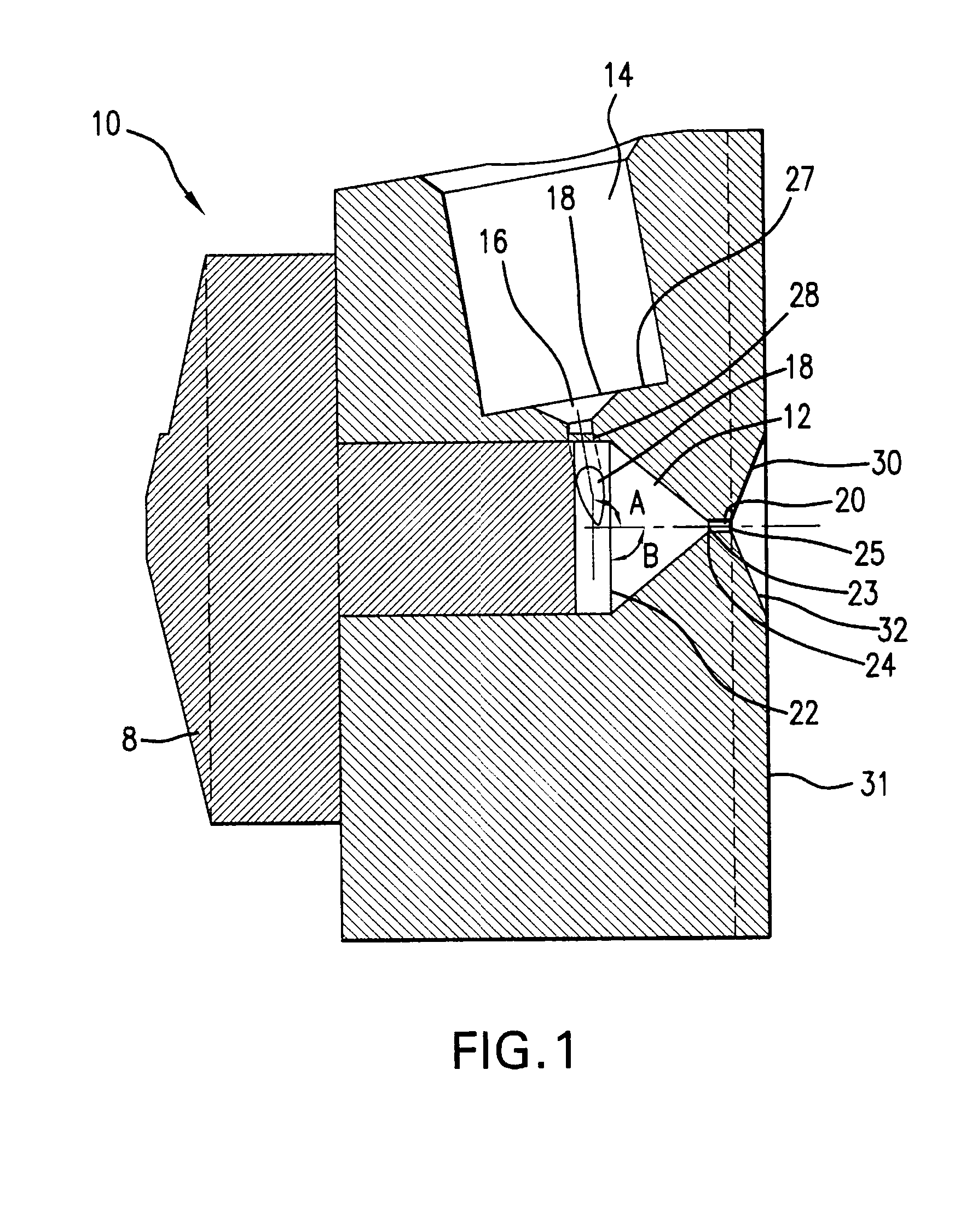
[0020]FIG. 1 illustrates a cross section of an atomization system described in U.S. Pat. No. 6,418,925. The components of the atomization system of FIG. 1 will be consistent throughout the other Figures as follows: Nozzle 10 receives pressurized liquid through nozzle inlet 14. which has a reducing chamber 16. Reducing chamber 16 includes of a reducing chamber inlet 26, a reducing chamber outlet 28, and a reducing chamber exit 18 that is attached tangentially to swirl chamber 12 and is the point at which the pressurized liquid exits the inlet 14 and enters the swirl chamber 12. The axis of the reducing chamber outlet 28 is set at an angle A to the axis of the swirl chamber 12. Angle A is greater than 90 degrees, preferably 105 degrees.

[0021]The swirl chamber is preferably conical, where the first swirl chamber end 22 is greater than the second swirl chamber end 24. The swirl chamber cone angle B is 60 to 120...


PUM


Abstract

An improved atomization system for aerosolizing liquids including a vortexing nozzle and a flat or protruding face on the nozzle exit orifice. The system can also include a diverging mouthpiece insert. The present invention can produce a high fine particle fraction and modest throat deposition in conjunction with reduced aerosol plume velocity and impact force.

Description

CROSS-REFERENCE SECTION TO RELATED APPLICATIONS[0001]This application claims priority to U.S. Application Ser. No. 60 / 903,970, filed Feb. 28, 2007, and is incorporated herein by reference in its entirety.FIELD OF THE INVENTION[0002]The invention relates to an atomization system for pressurized spray for use in various applications, including pharmaceutical applications involving pressurized metered dose inhalers, which reduces aerosol plume velocity and increases efficiency of spray delivery.BACKGROUND OF THE INVENTION[0003]Pressurized metered dose inhalers (“pMDIs”) are common in the industry, as are conventional MDI actuators that are based on “two-orifice-and-sump” designs. Unfortunately, their commonality is accompanied by their common disadvantages: high spray velocity and inadequate particle size distribution control, which results in poor drug delivery to the patient. It is postulated that high spray velocity is one of the lead causes of high oropharyngeal drug deposition (Ne...

Claims


Application Information

Patent Timeline
Patent Type & Authority Applications(United States)
IPC IPC(8): B05B1/34
CPCA61M15/009A61M2206/16A61M15/0021B05B1/3421B65D83/30B05B1/00A61M11/002
Inventor KAKADE, PRASHANT P.WILLIAMS, ROBERT C.GENOVA, PERRY
Owner ABBOTT LAB INC
Learn More