
Multi-Nozzle Liquid Droplet Ejecting Head, a Writing Instrument Comprising Such a Head, and a Method of Ejecting Liquid Droplets From Same

Inactive Publication Date: 2008-08-28
SOC DITE SOC BIC +1
View PDF4 Cites 1 Cited by
  • Summary
  • Abstract
  • Description
  • Claims
  • Application Information

AI Technical Summary

Benefits of technology

[0007]The head retains a classic actuator arrangement, except that the final droplet is a result of the combination of a plurality of ejected droplets from a number of nozzles. The plurality of ejected droplets can combine anywhere in the gap existing between the head and the support, or even combine at the point of contact with the support. Bigger, and therefore heavier, droplets will be ejected, and they will travel further and truer than smaller droplets. This is an important advantage when using hand-held writing instruments where distances between the liquid droplet ejecting head and the writing surface are generally far larger than applications where traditional ink ejection technology is used, such as desk inkjet printers.
[0008]A further advantage of this configuration is that by combining a plurality of simultaneous droplets together on or before the support, a bigger single spot is formed thereon, i.e. without blanks visible between the individual droplets, as can be the case with traditional ejectors. This enables us to draw a thicker line, or to operate the head at a lower ejecting frequency.
[0009]It should also be noted that this embodiment of the present invention allows for the use of typically-sized actuators, such as those used in desktop inkjet printers, to create bigger-than-typical sized drops by combining many small ejected droplets into bigger final droplets. Because of the smaller actuator size, this allows for greater positioning and arranging freedom of the actuators within a liquid droplet ejecting head.
[0010]A supplementary advantage is the possibility to vary the volume of the final ejected droplets as a function of user-input or deduced outcome by having the option of actuating a different number of actuators at each ink firing, and have a single drop of varying size contact a support. This is especially useful to mark lines of varying thickness without having to vary frequency.
[0011]All the while, the structural arrangement remains as in classical devices, whereby the path of ink is very direct from the reservoir to the nozzle, for greater reliability.DESCRIPTION OF THE PREFERRED EMBODIMENTS

Problems solved by technology

However, this does not resolve the problem that they still face of ejecting over greater distances.

Method used


Image

  • Multi-Nozzle Liquid Droplet Ejecting Head, a Writing Instrument Comprising Such a Head, and a Method of Ejecting Liquid Droplets From Same
  • Multi-Nozzle Liquid Droplet Ejecting Head, a Writing Instrument Comprising Such a Head, and a Method of Ejecting Liquid Droplets From Same
  • Multi-Nozzle Liquid Droplet Ejecting Head, a Writing Instrument Comprising Such a Head, and a Method of Ejecting Liquid Droplets From Same

Examples


first embodiment

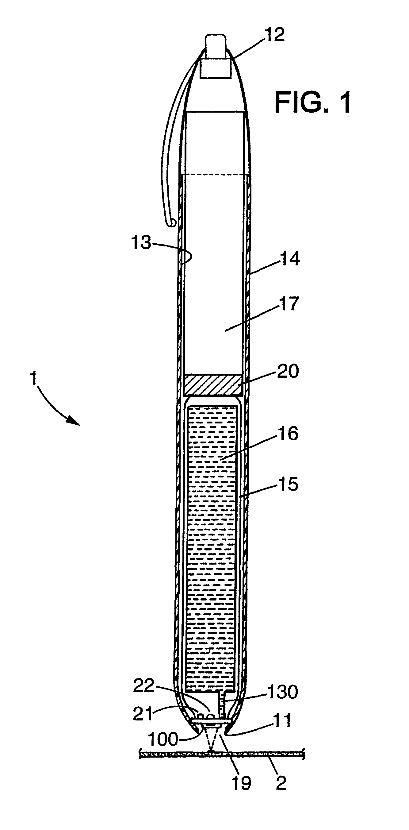
[0040]FIG. 1 is a sectional representation of a writing instrument comprising an ejection head ;

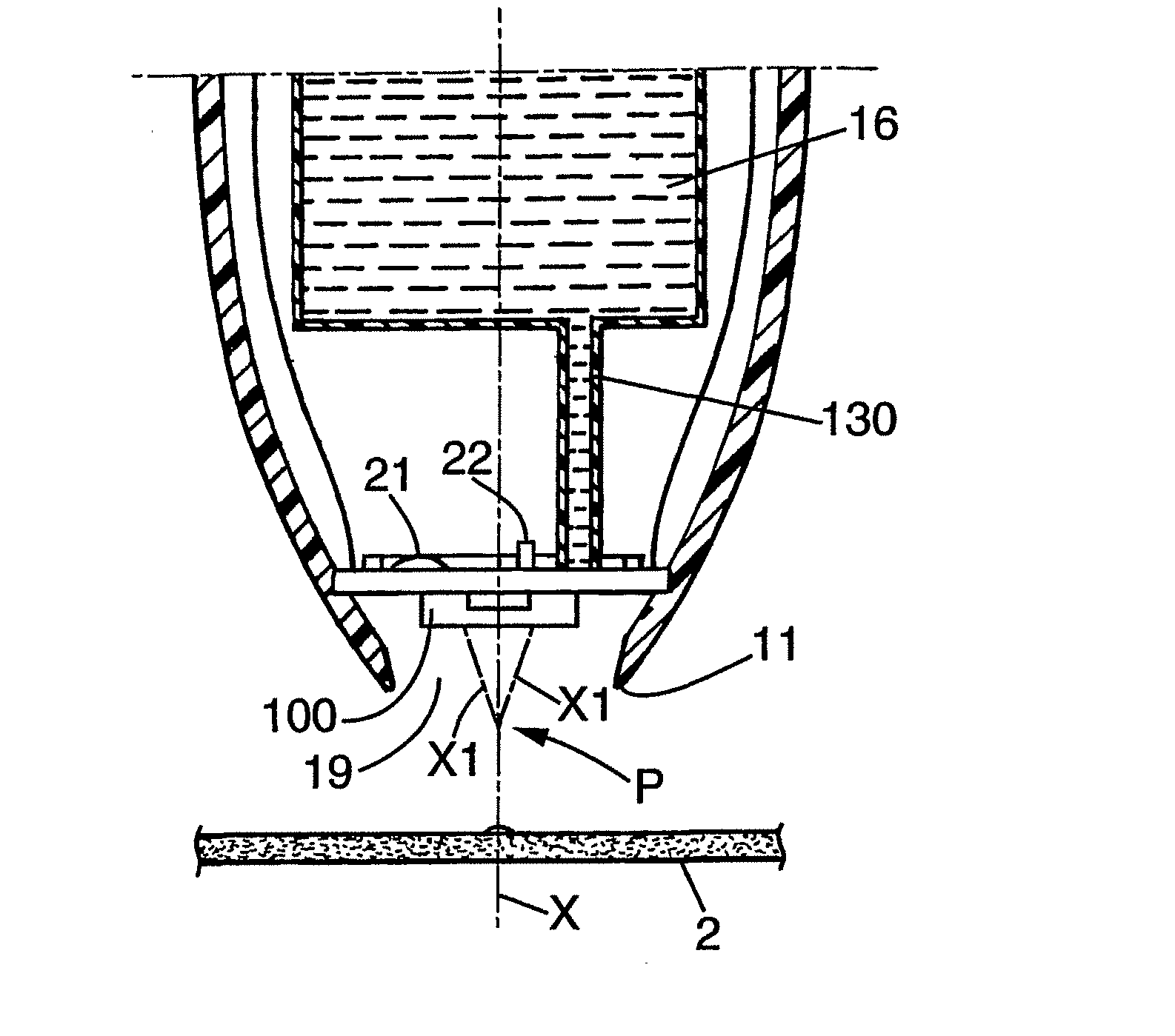
[0041]FIG. 2 is a more detailed view of the embodiment in FIG. 1, wherein the ejected droplets combine at a point situated before the support;

second embodiment

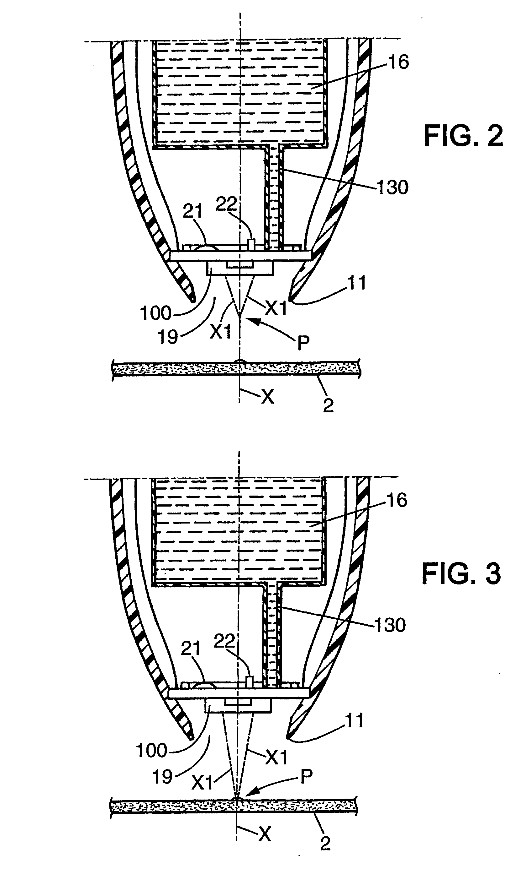
[0042]FIG. 3 is the same view as in FIG. 2 of a second embodiment, wherein the ejected droplets combine at a point situated on the support;

[0043]FIG. 4 shows a perspective view of the ejection head comprising a cover plate and a base plate.

[0044]FIG. 5 shows the same perspective view as in FIG. 4, with the cover plate removed.

[0045]On each of the figures, the same reference numerals refer to identical or similar elements.

[0046]FIG. 1 represents a particular embodiment of a liquid droplet ejecting head 100 mounted in a non-contact writing instrument 1. However, this embodiment of the present invention is not limited to writing instruments, and it would be apparent to those skilled in the art that this is but one possible embodiment that has equally valid uses in handheld printers, desktop printers, correction devices, painting devices or other instruments which releases liquid onto a support without physical contact between the instrument and the support.

[0047]The writing instrument ...


PUM


Abstract

A liquid droplet ejecting head designed to be mounted in a liquid ejecting instrument that includes ejection nozzles through which droplets are to be ejected from the head, and actuating chambers, each actuating chamber having at least one inlet to be in fluidic connection with a liquid reservoir for providing liquid to the actuating chamber. The ejecting head also includes at least one actuating unit suitable for creating a pulse wave in the liquid contained when activated by energy received from a control device and at least one outlet portion in fluidic connection with at least one ejection nozzle.

Description

CROSS-REFERENCE OF RELATED APPLICATION[0001]This application is a national stage application of International Application No. PCT / EP2005 / 010062, filed on Sep. 14, 2005, the entire contents of which are incorporated herein by reference.FIELD OF INVENTION[0002]The embodiments of the present invention relate to liquid droplet ejecting heads, and to liquid droplet ejecting instruments comprising such heads. More particularly, the embodiments of the present invention also relate to methods of ejecting liquid droplets from such liquid droplet ejecting heads.BACKGROUND OF INVENTION[0003]More particularly, the embodiments of the present invention relate to a liquid droplet ejecting head designed to be mounted in a liquid ejecting instrument, comprising a plurality of ejection nozzles through which droplets are to be ejected from the head, and a plurality of actuating chambers, each actuating chamber having at least one inlet to be in fluidic connection with a liquid reservoir for providing ...

Claims


Application Information

Patent Timeline
IPC IPC(8): B41J2/04
CPCB41J29/28B41J2/1433B41J3/36B41J29/023B41J3/44B41J29/393B41J2/04526B41J2/1404B41J2/485B41J2/0451B43K8/22
Inventor ROSENZWEIG, ALAINRATH, KURTBROOKS, COLINHILLS, ANDY
Owner SOC DITE SOC BIC
Learn More