Optical transmission system and optical transmission method

a transmission system and optical transmission technology, applied in the field of optical transmission systems and optical transmission methods, can solve the problems of skewing of optical packets arriving, increase in the scale of switching itself, and increase in the number of switching ports

Inactive Publication Date: 2008-08-28
FUJITSU LTD
View PDF8 Cites 18 Cited by
  • Summary
  • Abstract
  • Description
  • Claims
  • Application Information

AI Technical Summary

Problems solved by technology

With this configuration, however, broadening of the bandwidth entails increase in the number of switching ports, and increase in the scale of switching itself.
However, when signals are switched and merged in the optical region, the absence of a buffer element (delay element) which can hold the optical signals as they are causes skew to occur in the optical packets arriving at the input ports of the switch and the merging unit.
Since no information is transmitted during the guard period, the increase in guard period adversely affects optical packet transmission efficiency significantly.
However, when an optical packet signal in which signals of different wavelengths are multiplexed is used in the interconnect system using the optical packet switching described above to efficiently increase the band, a skew occurs in the wavelength-multiplexed signal before it arrives at a destination node.

Method used


Image

  • Optical transmission system and optical transmission method
  • Optical transmission system and optical transmission method
  • Optical transmission system and optical transmission method

Examples


first embodiment

[0030]Thus, the optical transmission system can correct the skew that occurs in the multiplexed optical-packet signal during transmission by adjusting the delay amount of each optical packet of the multiplexed optical-packet signal transmitted from the transmitting node to the receiving node based on the skew amount of each optical packet subjected to the optical wavelength multiplexing.

[0031]As the optical transmission system according to the first embodiment can correct the skew that occurs in the multiplexed optical-packet signal during transmission, the bands can be increased through the wavelength multiplexing technology. Further, the optical transmission system according to the first embodiment is capable of correcting the skew occurs in multiplexed optical-packet signal transmitted over any channel, thereby improving network utilization efficiency.

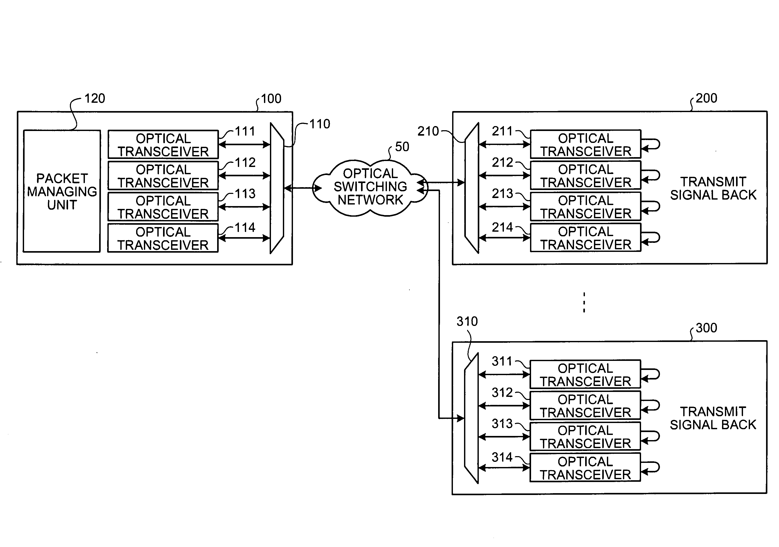
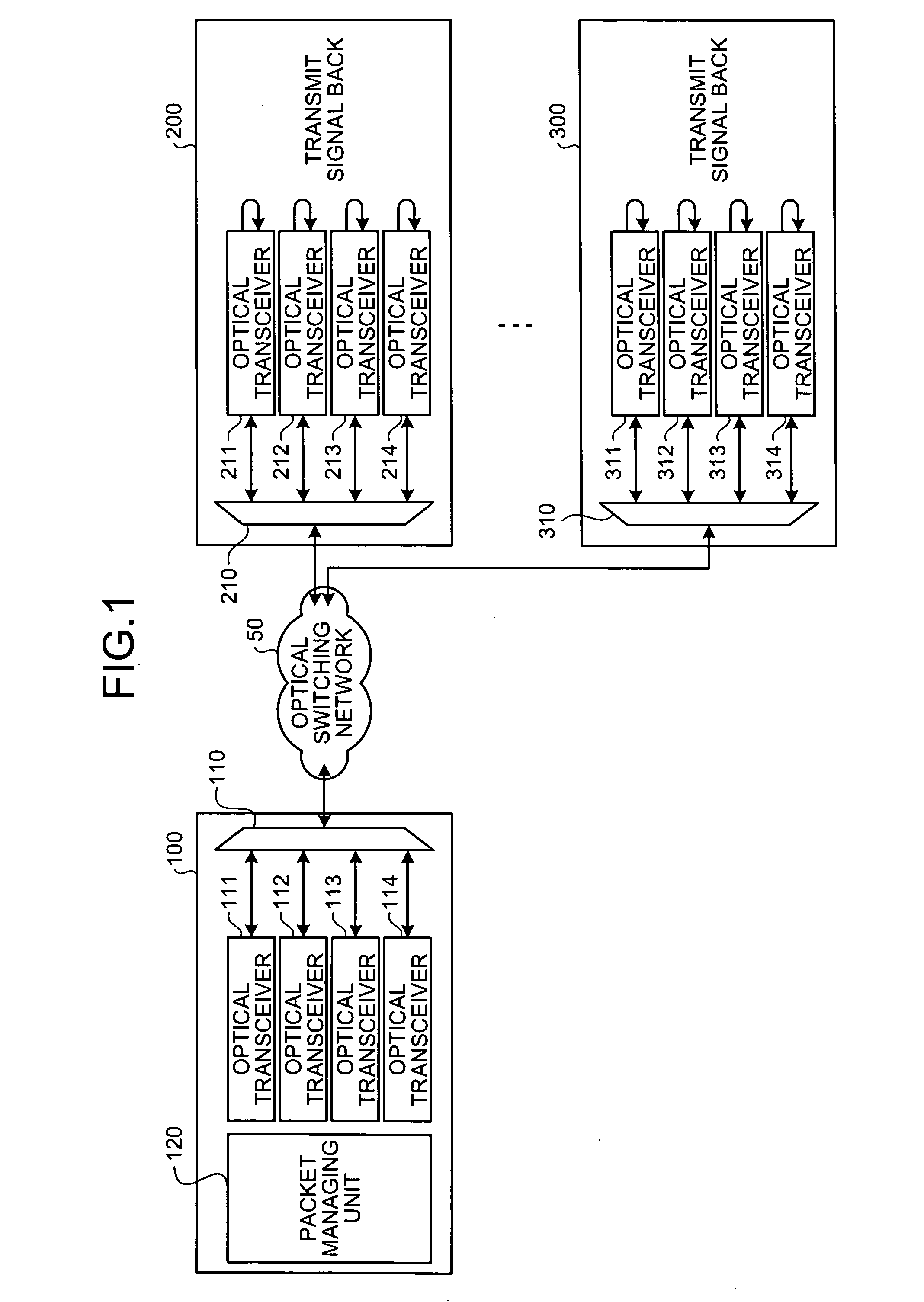
[0032]A configuration of the optical transmission system according to the first embodiment is described below. FIG. 1 is a diagra...

second embodiment

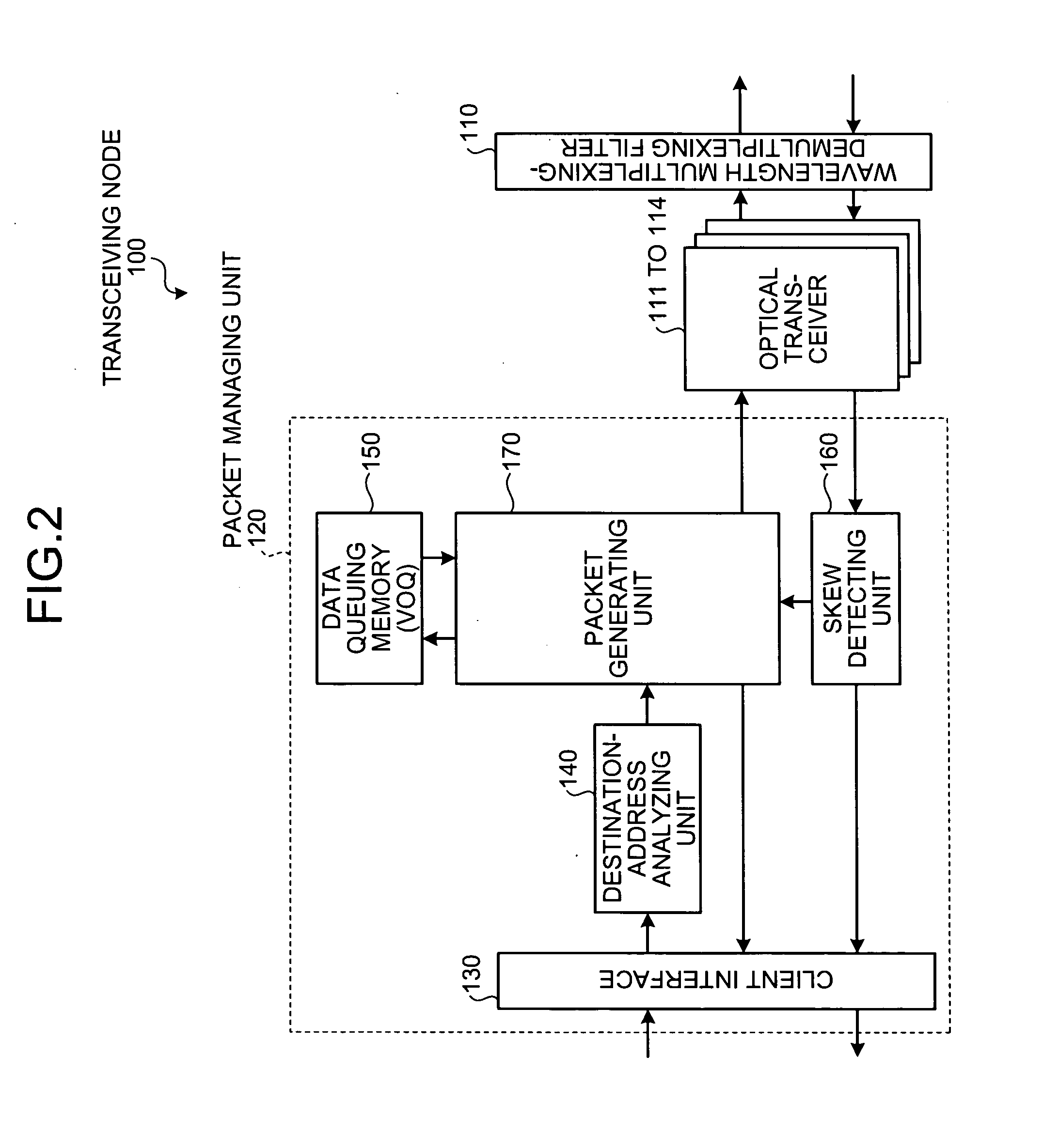
[0098]A detailed configuration of the transceiving node shown in FIG. 7 is described below. FIG. 8 is a functional block diagram of the transceiving node according to the As shown in FIG. 8, the transceiving node 400 includes the wavelength multiplexing-demultiplexing filter 410, the optical transceivers 411 to 414, and the packet managing unit 420.

[0099]The functions of the wavelength multiplexing-demultiplexing filter 410 and the optical transceivers 411 to 414 have already been described with reference to FIG. 7, and hence the descriptions thereof are not repeated.

[0100]The packet managing unit 420 includes a client interface 430, a destination-address analyzing unit 440, a data queuing memory (VOQ) 450, a skew detecting unit 460, an external-control IF unit 470, a control-ch optical module 480, a packet generating unit 490, a skew correcting unit 493, and an electrical-signal delay element 495.

[0101]The client interface 430 performs data communication between the packet managin...


PUM


Abstract

In an optical transmission system, a transmitting transceiving node generates a multiplexed optical-packet signal by performing optical wavelength multiplexing on a plurality of optical packets, and transmits the multiplexed optical-packet signal to a receiving transceiving node. The receiving transceiving node transmits the multiplexed optical-packet signal back to the transmitting transceiving node. The transmitting transceiving node detects a skew amount of the optical packet allocated to each wavelength band of the multiplexed optical-packet signal received from the receiving transceiving node, and adjusts a delay amount of the optical packet based on the detected skew amount.

Description

BACKGROUND OF THE INVENTION[0001]1. Field of the Invention[0002]The present invention relates to an optical transmission system and an optical transmission method for performing optical transmission over an optical switching network, and more particularly, to an optical transmission system and an optical transmission method that can perform correction of skew that can occur in wavelength-multiplexed signals.[0003]2. Description of the Related Art[0004]Adaptation of optical interconnects is under review for interconnect systems of parallel computers such as supercomputers and signal switching in high-speed routers to avoid bottleneck (in terms of band and physical amount, for example) in electric wiring technology. The optical interconnect utilizes the broadband property of optical transmission technology. The optical interconnect is a generic term for optical data communication of extremely short distance. In general, the optical interconnect means optical communication of a distanc...

Claims


Application Information

Patent Timeline
Patent Type & Authority Applications(United States)
IPC IPC(8): H04J14/00H04B10/00H04B10/07H04B10/077H04B10/079H04B10/2507H04B10/2513H04B10/524H04J14/02
CPCH04Q11/0005H04Q11/0066H04Q2011/005H04Q2011/0039H04Q2011/0045H04Q2011/003
Inventor AOKI, YASUHIKO
Owner FUJITSU LTD
Why Eureka
Try Eureka