Array Antenna System and Spread Spectrum Beamformer Method

a beamformer and array antenna technology, applied in the field of array antennas with digital beamformers, can solve the problems of receive array antennas with digitally controlled analog beamformers that do not scale well to support, and array antennas with conventional digital beamformers that do not scale well to higher frequencies. achieve the effects of spreading spectrum processing gain, simple design, manufacture and testing, and simple structur

Inactive Publication Date: 2009-04-23
APPLIED RADAR
View PDF7 Cites 212 Cited by
  • Summary
  • Abstract
  • Description
  • Claims
  • Application Information

AI Technical Summary

Benefits of technology

[0010]The overall object of this invention is an array antenna with digital beamforming capabilities that uses a single transceiver with one low noise amplifier (LNA) / one power amplifier (PA), one up / down frequency converter and one pair of analog-to-digital and digital-to-analog converters for the entire array. The spread spectrum beamformer method performs the multiplexing of signals to / from each array element with minimum hardware at the array elements and enables the implementation of array antennas with digital beamforming capabilities that are thin and scales large arrays and to high frequencies.
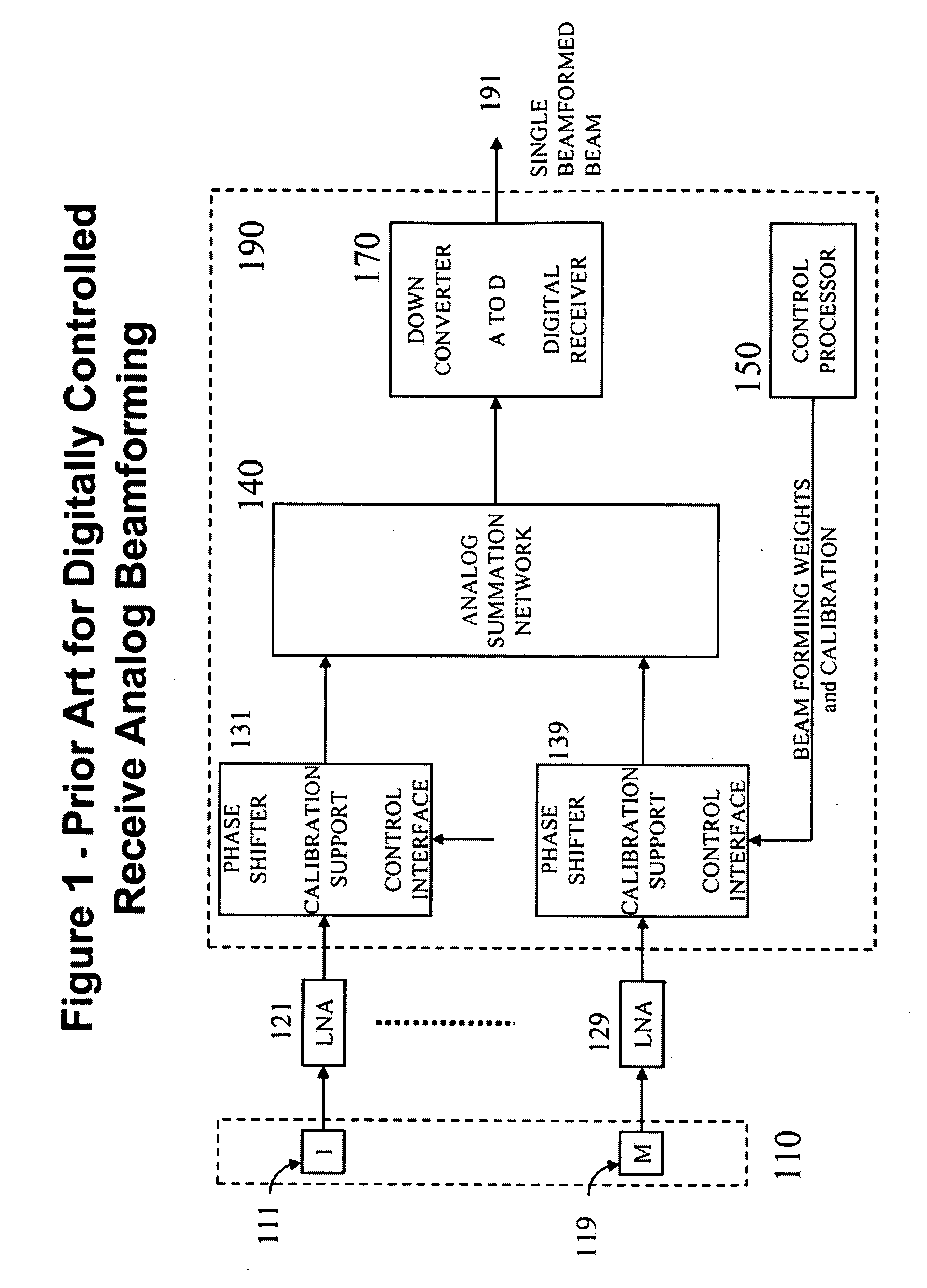
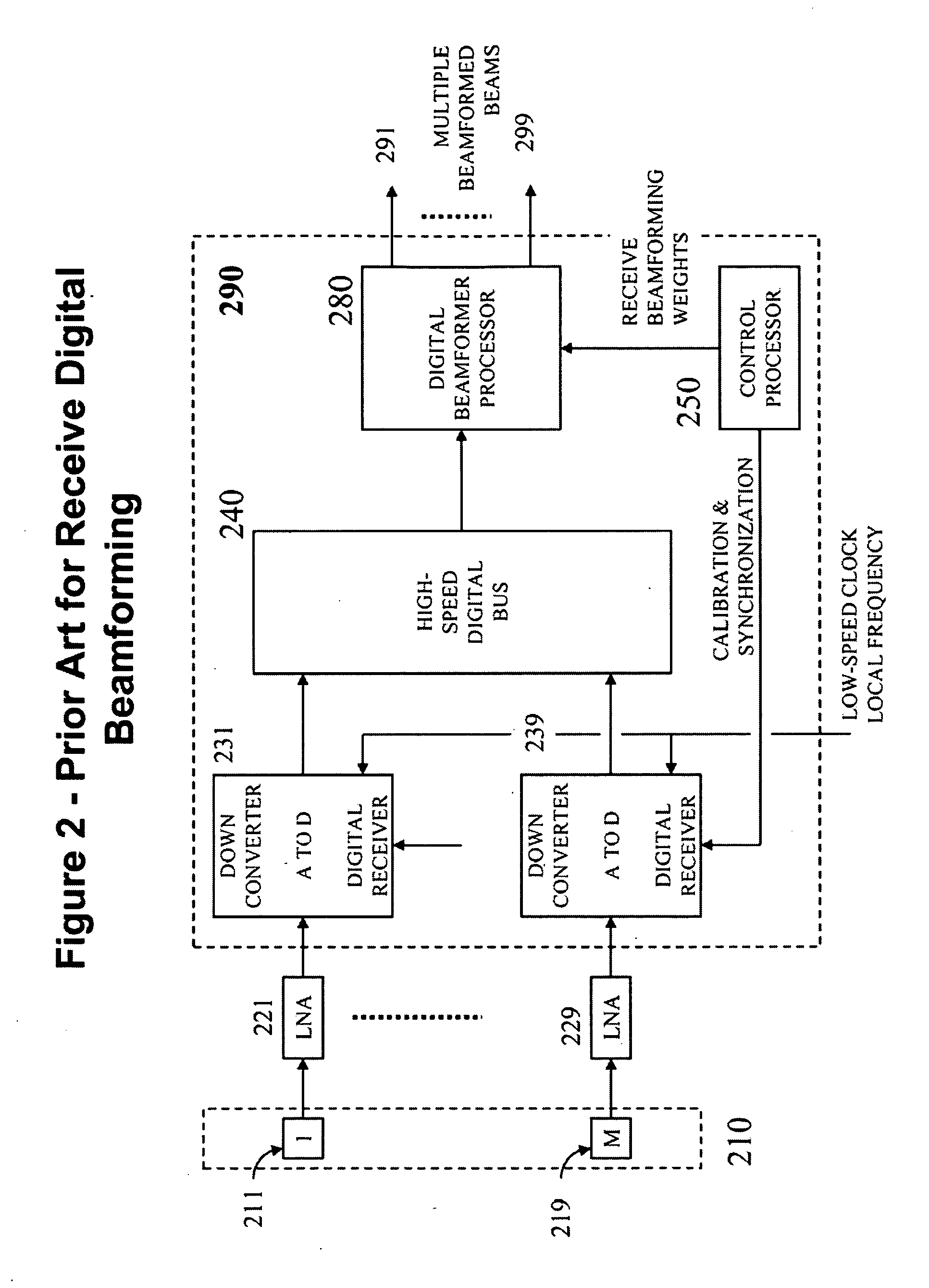
[0011]Accordingly, the method object of this invention applies to radars, sensors and communication systems equipped with array antennas. One aspect that differentiates this invention from prior art as applied to digital beamforming is the method of using direct-sequence spread spectrum for both transmission and multiplexing inside arrays with spaced apart array elements. This enables digital beamforming with capability and performance comparable to or better than array antennas using prior art digital beamforming technologies with the advantage that, contrary to prior art, the array antennas DO NOT require a digital transceiver including LNA / PA, up / down frequency converter and analog-to-digital / digital-to-analog converters at each array element or sub-array and, as a result, are simpler to design, manufacture and test; scale up in frequency and in number of elements; scale down in power, weight, thickness and heat dissipation.
[0014]It is an object of this invention that, when receiving, incident signals at each element are enabled to be multiplexed directly at the frequencies in which they are received, and then extracted without mutual interference while being subject to negligible noise-relate performance degradation. This enables the implementation of low-profile receive array antennas as the low noise amplifier and the digital receiver electronics including down-converter and analog-to-digital converter can be placed remotely from the actual antenna array elements.
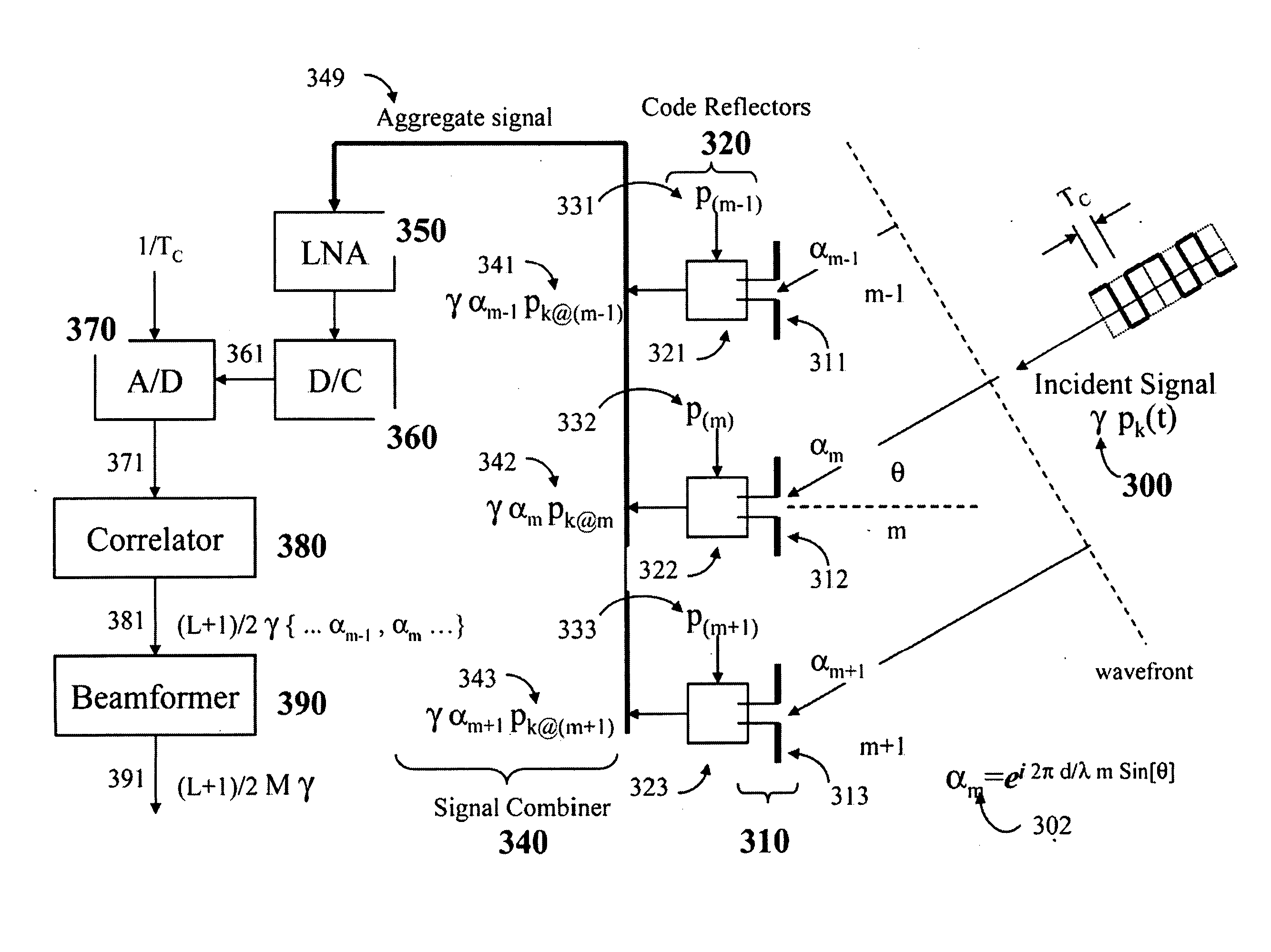
[0020]The receive system includes a receive array apparatus integrated with a method for generating direct-sequence spread spectrum signals comprised of a multitude of pseudo-noise sequences with a common base sequence including maximal-length sequences with different cyclic shifts, and a method for receiving such spread spectrum signals from different positions including a multiplicity of transmitters at different locations while subjected to reflections from stationary obstacles and moving objects; generating reflected signals at the same carrier frequency as the incident signal while using reflecting signals with distinguishable spectrum features at each array element; combining such reflected signals into a common aggregate radio-frequency signal for the array using either wired or wireless means; converting the aggregate radio-frequency signal to a convenient intermediate frequency including baseband while using a single low noise amplifier and down-converter for the entire array; sampling the resulting aggregate baseband signal while using a single analog-to-digital converter operating at least at the Nyquist rate of the received signals; correlating such an aggregated baseband signal against sequences or variations thereof included in the aggregate radio-frequency signal while capturing angle-of-arrival and multipath information and achieving spread spectrum processing gain and multipath gain; and performing joint beamform and detection to estimate signals, data or parameters included in the incident signals including spatial nulling of a subset of such incident signals while achieving receive array gain. The resulting receive system apparatus and methods enable receive digital beamforming with capability and performance comparable to or better than receive arrays using prior art digital beamforming technologies with the advantage that, contrary to prior art, they DO NOT require a digital transceiver including LNA, down-converter and analog-to-digital converter at each element and, as a result, are simpler to design, manufacture and test; scale up in frequency and number of elements; scale down in power, weight, thickness and heat dissipation.
[0021]The transmit system includes a transmit array apparatus integrated with a spread spectrum multiplexing method for generating, aggregating, up-converting, amplifying, distributing and extracting a beamforming radio-frequency signal for each element of the array, a method for re-modulating the radio-frequency signal extracted at each element including corresponding beamforming weight as a direct-sequence spread spectrum signal while using codes that can be equal or different for each element, including codes comprising a pseudo-noise sequence with a different cyclic shift from a common base sequence including a maximal-length sequence, and a method for generating, amplifying and transmitting such extracted radio-frequency signals including resulting re-modulated spread spectrum signals as a sequence of short-duration high-power pulses while using a power amplification method comprised of passive components that combines segmenting a continuous radio-frequency signal in equal-duration wave-blocks, coherently accumulating the energy of each wave-block in a delay line, and then releasing the coherently accumulated energy as short-duration pulse per wave-block while achieving array gain and further bandwidth expansion as compared to the bandwidth of the original signal distributed to or generated at each element of the array. The resulting transmit system apparatus and methods enable transmit digital beamforming with capability and performance including radar-related time-and-frequency ambiguity resolution performance comparable to or better than transmit arrays using prior art digital beamforming technologies with the advantage that, contrary to prior art, they DO NOT require a digital transceiver including power amplifier, up-converter and digital-to-analog converter at each element and, as a result, are simpler to design, manufacture and test; scale up in frequency and number of elements; scale down in power, weight, thickness and heat dissipation.

Problems solved by technology

It is well understood that receive array antennas with digitally controlled analog beamformers do not scale well to support multiple beams, as they typically require-one complete analog beamformer including a multi-signal summation network per receive beam and a signal distribution network per transmit beam.
They also do not scale well to higher frequencies, as they require dedicated phase shifter hardware including control interface and calibration support electronics, and dedicated low noise amplifier and power amplifier per element.
It is common knowledge that array antennas with conventional digital beamformers-do not scale well to higher frequencies as they require one full digital receiver, including LNA, a down-converter and analog-to-digital converter per element or sub-array, and extensive support for calibrating and synchronizing such receivers.
It is common knowledge that array antennas with conventional digital beamformers do not scale well to higher frequencies as they require one full digital transceiver (i.e., transmitter and receiver), including dedicated LNA and PA, up and down frequency converters, and analog-to-digital and digital-to-analog converters per element or sub-array, and extensive support for calibrating and synchronizing each transceiver.
Conventional phased arrays using element-by-element weighting (amplitude, phase / delay) or digital beamforming (DBF) with a dedicated transceiver (including LNA / PA, up / down frequency converters and A / D and D / A converters) per element do not scale down well in power, real estate area for the electronics, heat dissipation and overall antenna thickness.
These conventional antenna solutions do not scale well either to support wideband signals as they worsen the requirements for signal distribution, synchronization, and frequency-conversion, and A / D and D / A speeds.

Method used


Image

  • Array Antenna System and Spread Spectrum Beamformer Method
  • Array Antenna System and Spread Spectrum Beamformer Method
  • Array Antenna System and Spread Spectrum Beamformer Method

Examples


Embodiment Construction

[0038]The objects of the invention include a receive array apparatus and receive beamforming methods, and a transmit array apparatus and transmit beamforming methods. FIGS. 3 through 10 apply to the receive system using spread spectrum. FIGS. 13 through 16 apply to the transmit system using spread spectrum multiplexing inside the array. FIGS. 1-2 and 11-12 illustrate receive arrays and transmit arrays using prior-art analog and digital beamforming methods.

Receive Array System

[0039]In general, the receive array object of this invention includes a wireless or a wired means for combining the signals reflected at each element while generating a single multi-level direct-sequence spread spectrum aggregate signal at the carrier frequency for the array.

[0040]FIG. 3 illustrates a receive array with a wired signal combiner in which the reflected signals result from the multiplication of the reflecting signal at each element with the incident signal. FIG. 4 illustrates a receive array with an...


PUM


Abstract

A method for transmitting digital beamformed signals in a transmit array antenna apparatus utilizing a single transceiver with one power amplifier, one up-frequency converter and one digital-to-analog converter for said array transmit antenna apparatus comprising the steps of: generating a first set of direct-sequence spread spectrum codes; generating a plurality of weights, each weight being a beamforming amplitude and phase or delay for each element; generating a direct-sequence spread spectrum multiplexed signal containing such weights while using one of such first-set codes per element; converting such an multiplexed signal to a convenient radio frequency; amplifying and transmitting such a multiplexed radio frequency signal to the elements; generating a second set of direct-sequence spread spectrum codes; extracting a radio frequency signal with direction-bearing weight information at each element while using a subset of codes from the second set; generating a third set of direct-sequence spread spectrum codes at each element; transmitting a signal with array gain beamformed towards a specific direction while using a transmit array apparatus composed of spaced elements, such a transmit beamformed signal being a radio frequency signal, a direct-sequence spread spectrum radio frequency signal containing a subset of codes from the third set, or a sequence of radio frequency pulses that have short duration and high power.

Description

FIELD OF THE INVENTION[0001]The present invention relates generally to array antennas with digital beamformers and their use in radar, sensor and communication applications, and particularly to radar, sensor and communication systems using direct sequence spread spectrum signaling and array antennas with digital beamformers using spread spectrum multiplexing within the array system. The apparatus and methods of this invention include methods for transmitting and receiving signals with antenna array gain and methods, devices and techniques for multiplexing the signals within the array apparatus.BACKGROUND OF THE INVENTIONPrior ArtAntenna Array with Digitally Controlled Analog Beamformer[0002]FIG. 1 illustrates a prior-art exemplary receive array 100 with digitally controlled analog beamformer 190. Typically, the phase shifters at each antenna have high insertion loss and must be preceded by a low-noise amplifier (LNA). The system includes an antenna array 110 with an arbitrary number...

Claims


Application Information

Patent Timeline
Patent Type & Authority Applications(United States)
IPC IPC(8): H04B1/707
CPCH04B1/707H04B7/0617H04J13/10H04J13/00H04B7/086
Inventor BERGAMO, MARCOS ANTONIO
Owner APPLIED RADAR
Why Eureka
Try Eureka