Transverse-mode multiplexing for optical communication systems

a technology of optical communication system and transverse mode, applied in multiplex communication, instruments, optical elements, etc., can solve the problem that the hardware for implementing optical mimo is not yet sufficiently developed

Active Publication Date: 2010-12-30
ALCATEL LUCENT SAS
View PDF32 Cites 215 Cited by
  • Summary
  • Abstract
  • Description
  • Claims
  • Application Information

AI Technical Summary

Benefits of technology

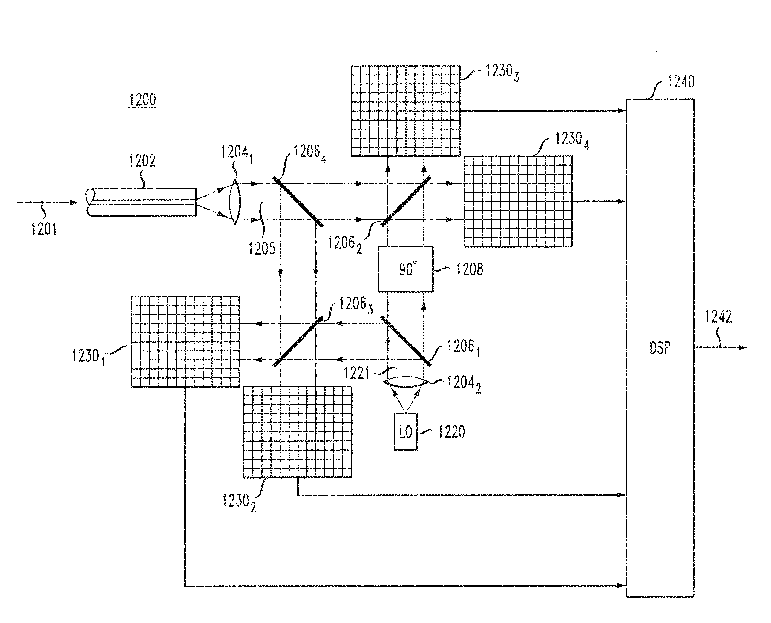
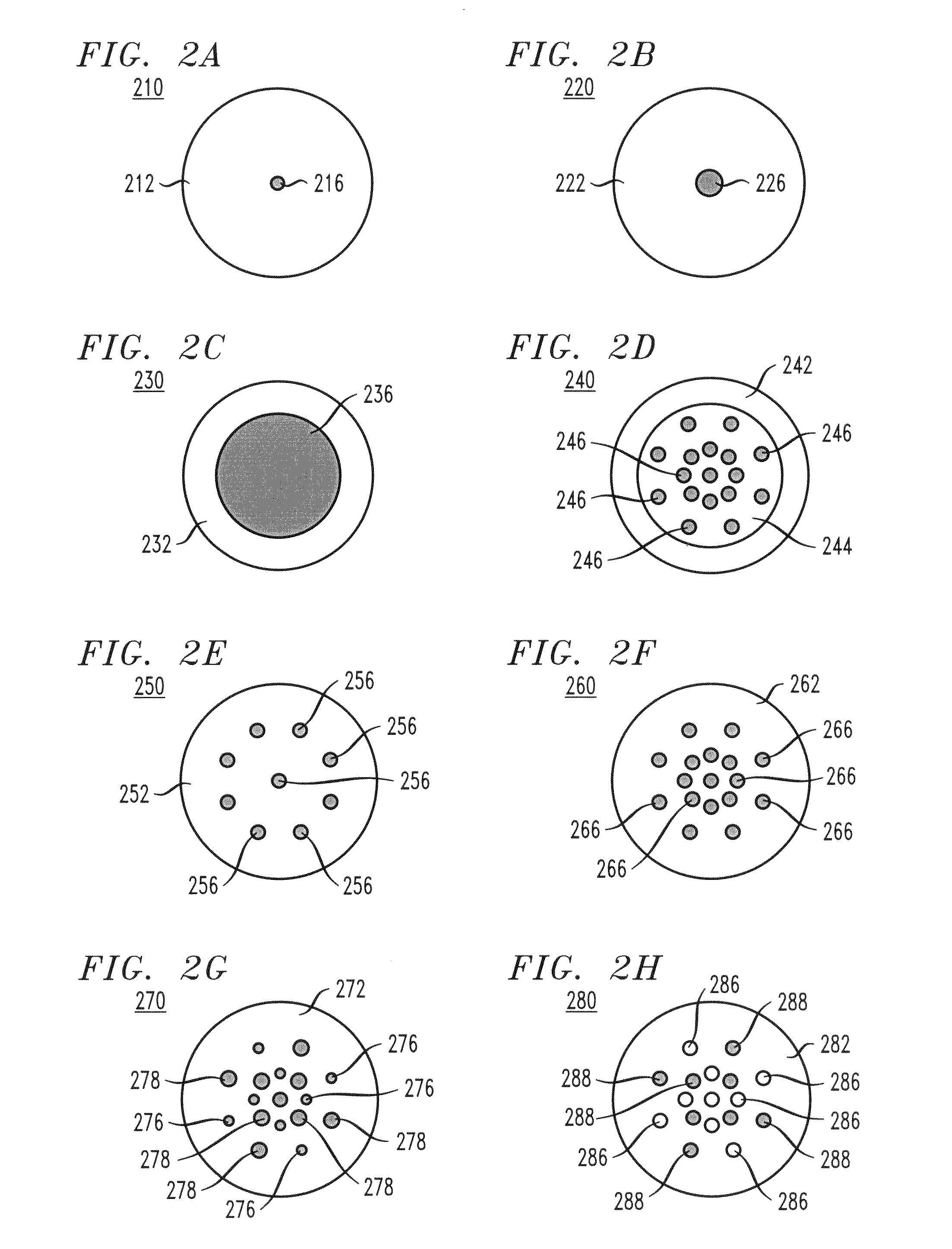
[0008]Disclosed herein are various embodiments of an optical communication system having an optical transmitter and an optical receiver optically coupled via a multi-path fiber. The optical transmitter launches, into the multi-path fiber, an optical transverse-mode-multiplexed (TMM) signal having a plurality of independently modulated components by selectively coupling each independently modulated component into a respective single transverse mode of the multi-path fiber. The TMM signal undergoes inter-mode mixing in the multi-path fiber before being received by the optical receiver. The optical receiver processes the received TMM signal to reverse the effects of inter-mode mixing and recover the data carried by each of the independently modulated components.

Problems solved by technology

However, the hardware for implementing optical MIMO is not yet sufficiently developed.

Method used


Image

  • Transverse-mode multiplexing for optical communication systems
  • Transverse-mode multiplexing for optical communication systems
  • Transverse-mode multiplexing for optical communication systems

Examples


Embodiment Construction

Optical Communication System

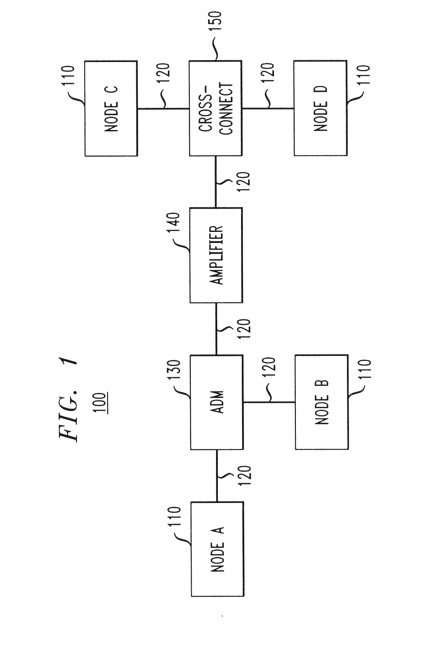
[0026]FIG. 1 shows a block diagram of an optical communication system 100, in which various embodiments of the invention can be practiced. System 100 has a plurality of communication nodes 110 interconnected via a network of optical communication links 120. System 100 further has an optical add / drop multiplexer (ADM) 130, an optical amplifier 140, and an optical cross-connect 150, all variously interposed between nodes 110.

[0027]Each node 110 has optical multiple-input multiple-output (MIMO) capabilities achieved through the use of transverse-mode multiplexing (TMM). Node110 generally includes an optical transmitter and an optical receiver (neither is explicitly shown in FIG. 1) to enable two-way communications between various nodes of system 100. In addition to TMM multiplexing, an individual node 110 might also use wavelength-division multiplexing (WDM) and / or polarization multiplexing (PM), or both. Representative embodiments of an optical transmitter ...


PUM


Abstract

An optical communication system having an optical transmitter and an optical receiver optically coupled via a multi-path fiber. The optical transmitter launches, into the multi-path fiber, an optical transverse-mode-multiplexed (TMM) signal having a plurality of independently modulated components by coupling each independently modulated component into a respective transverse mode of the multi-path fiber. The TMM signal undergoes inter-mode mixing in the multi-path fiber before being received by the optical receiver. The optical receiver processes the received TMM signal to reverse the effects of inter-mode mixing and recover the data carried by each of the independently modulated components.

Description

CROSS-REFERENCE TO RELATED APPLICATIONS[0001]The subject matter of this application is related to that of U.S. patent application Ser. No. 1______, by R.-J. Essiambre, R. Ryf, and P. Winzer, attorney docket reference 805512-US-NP, filed on the same date as the present application, and entitled “Receiver for Optical Transverse-Mode-Multiplexed Signals,” which application is incorporated herein by reference in its entirety.BACKGROUND[0002]1. Field of the Invention[0003]The present invention relates to optical communication equipment and, more specifically but not exclusively, to the equipment that enables transverse-mode multiplexing (TMM) in optical communication systems.[0004]2. Description of the Related Art[0005]This section introduces aspects that may help facilitate a better understanding of the invention(s). Accordingly, the statements of this section are to be read in this light and are not to be understood as admissions about what is in the prior art or what is not in the pri...

Claims


Application Information

Patent Timeline
Patent Type & Authority Applications(United States)
IPC IPC(8): H04J14/04H04B10/2581
CPCG02B6/14G02B6/2848H04B10/2581G02B6/2817H04J14/04G02B6/34H04B10/677G02B6/26H04B10/40
Inventor ESSIAMBRE, RENE'-JEANRYF, ROLANDWINZER, PETER J.
Owner ALCATEL LUCENT SAS
Why Eureka
Try Eureka