
Cannula Having Unbreakable Tip

a cannula and tip technology, applied in the field of surgical instruments, can solve the problems of reducing the strength of the suture, fending off the suture, and causing the suture to break

Inactive Publication Date: 2008-08-28
POWERS DAVID M +1
View PDF5 Cites 12 Cited by
  • Summary
  • Abstract
  • Description
  • Claims
  • Application Information

AI Technical Summary

Benefits of technology

[0012]An important object of the invention is to provide a cannula for use in surgical procedures that will not break upon encountering a bone or other hard object.
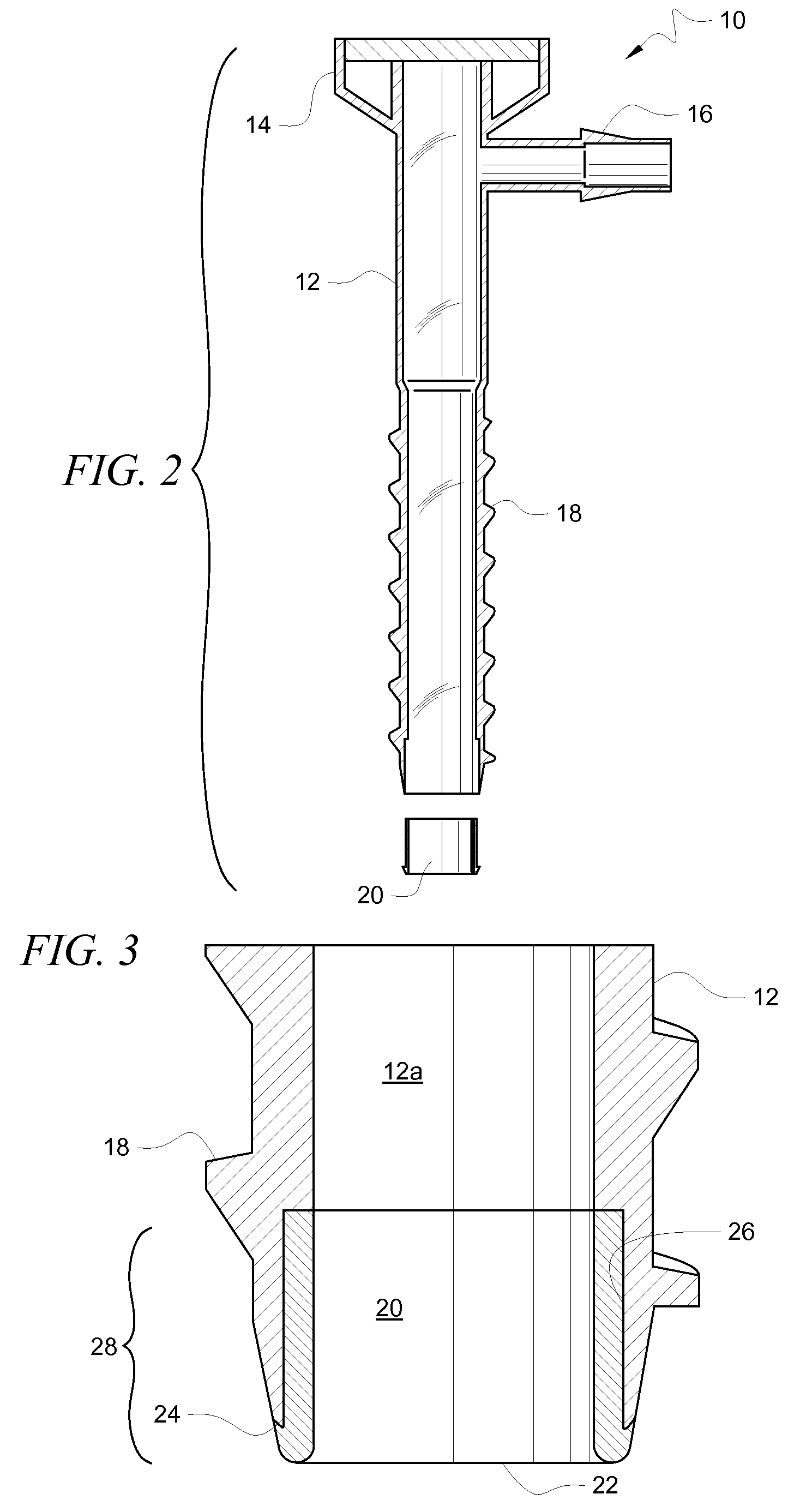
[0014]Another object is to provide a protective distal tip that has a lumen that lies flush with a lumen of the cannula body so that the protective distal tip does not obstruct surgical tools or implements that are fed through the lumen of the cannula body.

Problems solved by technology

Such rubbing frays the suture and reduces its strength.
The rubbing can also cause the suture to break.
This causes an additional cost to the hospital and the patient.
Moreover, the replacement anchor will not be as ideally positioned as the first, no-longer-usable anchor because the surgeon will have positioned the first anchor in an optimal location.
Conventional cannulas are also subject to breakage at their distal tip.
Breakage may occur if a surgeon hits a bone with sufficient force to cause such breakage.
Introducing an orthopedic instrument into the lumen of the cannula during arthroscopic repair of a rotator cuff or labrum may also break the tip of a conventional cannula.
If the cannula is chipped during such a procedure, the result is a loose body of plastic floating around in the shoulder joint of the patient.
The plastic must be removed and such removal can take a long time.

Method used


Image

  • Cannula Having Unbreakable Tip
  • Cannula Having Unbreakable Tip
  • Cannula Having Unbreakable Tip

Examples


Embodiment Construction

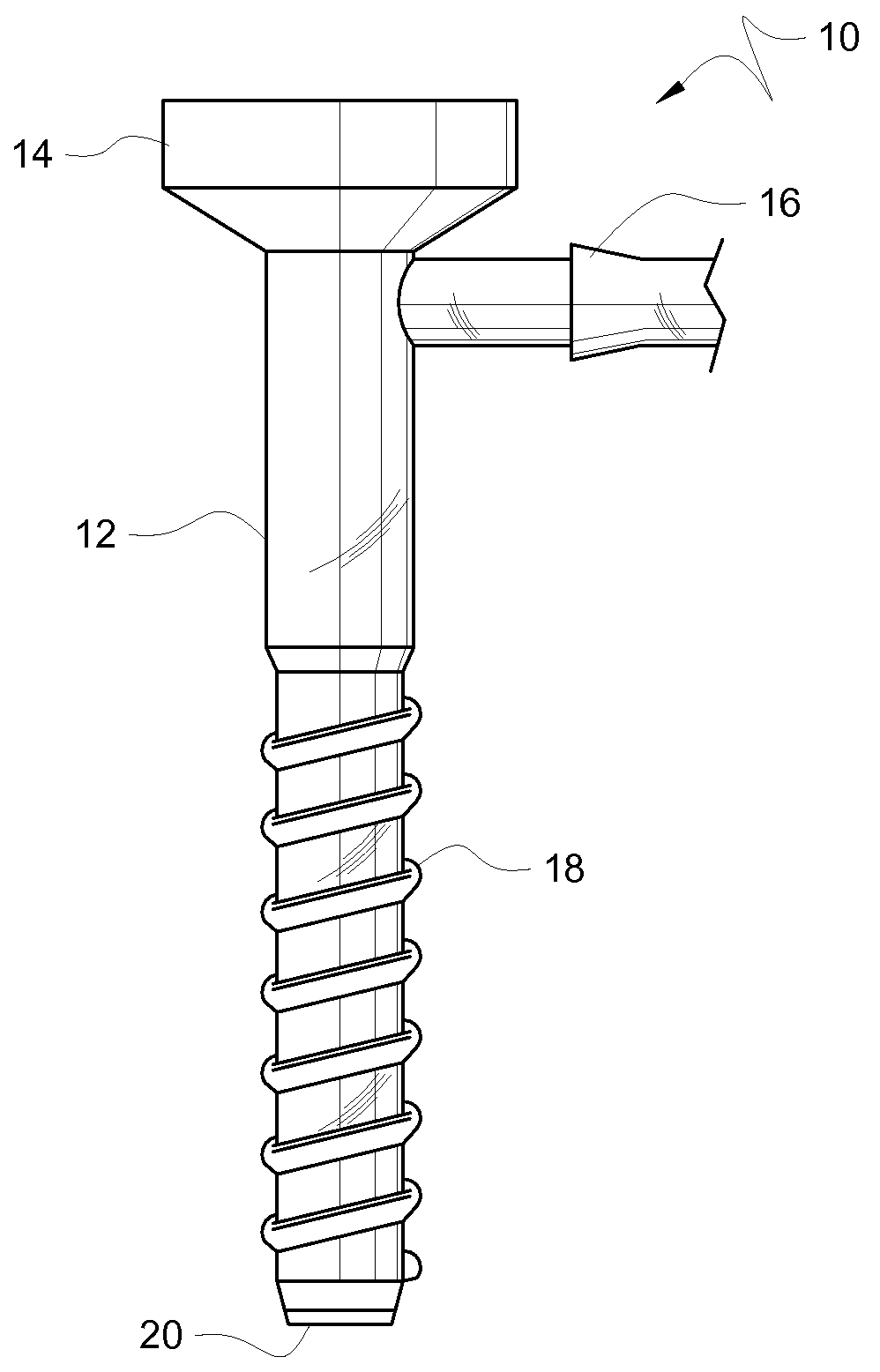
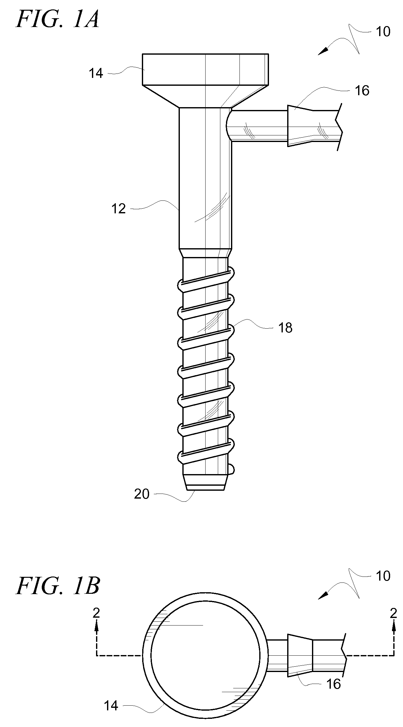
[0023]Referring now to FIGS. 1A and 1B, there it will be seen that an illustrative embodiment of the invention is denoted as a whole by the reference numeral 10.

[0024]Cannula 10 includes elongate cannula body 12 formed of a translucent or transparent polycarbonate plastic. Funnel-shaped head 14 is formed at the proximal end of cannula body 12 and port 16 extends radially from said cannula body. Helical threads 18 are formed in the leading half of cannula body 12. Head 14, port 16, and threads 18 are conventional and form no part of the invention, per se.

[0025]Cannula body 12 and threads 18 formed integrally therewith are preferably formed of polycarbonate.

[0026]Distal tip 20 overlies and protects the sharp distal end of cannula body 12. Said distal tip is preferably formed of thermoplastic urethane or thermoplastic urethane rubber.

[0027]The thermoplastic urethane structure of distal tip 20 acts like a windshield. It prevents the polycarbonate of which cannula body 12 is formed from ...


PUM


Abstract

A cannula includes an elongate cannula body formed of a translucent polycarbonate plastic having a distal end and the distal end has a sharp edge that frays and weakens sutures that rub against it. A distal tip has a rounded leading end and is disposed in overlying, protective relation to the distal end of the cannula body and the sharp edge. The distal tip is formed of a material that is substantially unbreakable upon contact with bone or other hard material encountered during surgery. The material may be a metal, a thermoplastic urethane or a thermoplastic urethane rubber. An annular recess formed in a lumen of the cannula body at the distal end of the cannula body accommodates the distal tip so that the lumen of the cannular body and the lumen of the distal tip are flush with one another.

Description

BACKGROUND OF THE INVENTION[0001]1. Field of the Invention[0002]This invention relates to surgical instruments. More particularly, it relates to a cannula having a tip that does not break or chip when used in a surgical procedure.[0003]2. Description of the Prior Art[0004]An anchor is an implant used in orthopedic surgery. It is screwed into a humeral head by a surgeon performing a rotator cuff repair or into the glenoid if performing a labral repair.[0005]Cannulas are commonly used in arthroscopic surgery. The distal end of a conventional cannula terminates in a tip having a sharp inner edge. When a suture is used, it can rub against such sharp inner edge. Such rubbing frays the suture and reduces its strength. The rubbing can also cause the suture to break. If the suture is secured to an anchor, the patient is charged for an additional suture and a new anchor. Depending upon the manufacturer, an anchor to repair a rotator cuff or labrum ranges from $150.00 to $400.00. When the sut...

Claims


Application Information

Patent Timeline
IPC IPC(8): A61B17/34
CPCA61B17/3421A61B2017/349A61B2017/00902A61B2017/00831
Inventor POWERS, DAVID M.VAN MEER, GARY
Owner POWERS DAVID M
Learn More