Method of starting a gas turbine helicopter engine, a fuel feed circuit for such an engine, and an engine having such a circuit

Inactive Publication Date: 2008-09-04
TURBOMECA SA
View PDF2 Cites 7 Cited by
  • Summary
  • Abstract
  • Description
  • Claims
  • Application Information

AI Technical Summary

Benefits of technology

[0009]after ignition, eliminating said head loss imposed between the feed pipe and the other main injectors so that all of the main injectors are fed with fuel at substantially the same pressure, without any imposed head loss.
[0010]Since one of the main injectors is used as a starter injector, there is no need to provide specific starter injectors, and thus no need to provide means for purging them after starting. Furthermore, the level valve is active only while starting. In normal operation, no extra pressure is required in the feed pipe since there is no imposed head loss. Compared with the prior art fuel feed circuit, the output pressure from the pump can thus be lowered and / or a greater pressure can be made available to the main injectors for improving the spraying of fuel.
[0011]In an implementation of the method, the head loss is imposed by interposing a level valve between the pressurized feed pipe and the other main injectors, and the head loss is eliminated by closing an on / off valve in a pipe bypassing the level valve.
[0015]a control circuit for the on / off valve is provided to select between the head loss that is imposed by the level valve being applied and being eliminated.
[0016]The invention also provides a gas turbine helicopter engine including a combustion chamber and a circuit for feeding fuel to the combustion chamber as defined above, in particular an engine with a combustion chamber having gyratory air flow. A gyratory flow of air in the combustion chamber encourages the propagation of the flame generated by the starter main injector to all of the other main injectors.

Problems solved by technology

It is necessary to purge the starter injectors in order to avoid fuel coking as would happen if they were not purged, which coking could harm subsequent proper operation of the starter injectors because of the solid deposits formed.

Method used


Image

  • Method of starting a gas turbine helicopter engine, a fuel feed circuit for such an engine, and an engine having such a circuit
  • Method of starting a gas turbine helicopter engine, a fuel feed circuit for such an engine, and an engine having such a circuit
  • Method of starting a gas turbine helicopter engine, a fuel feed circuit for such an engine, and an engine having such a circuit

Examples


Embodiment Construction

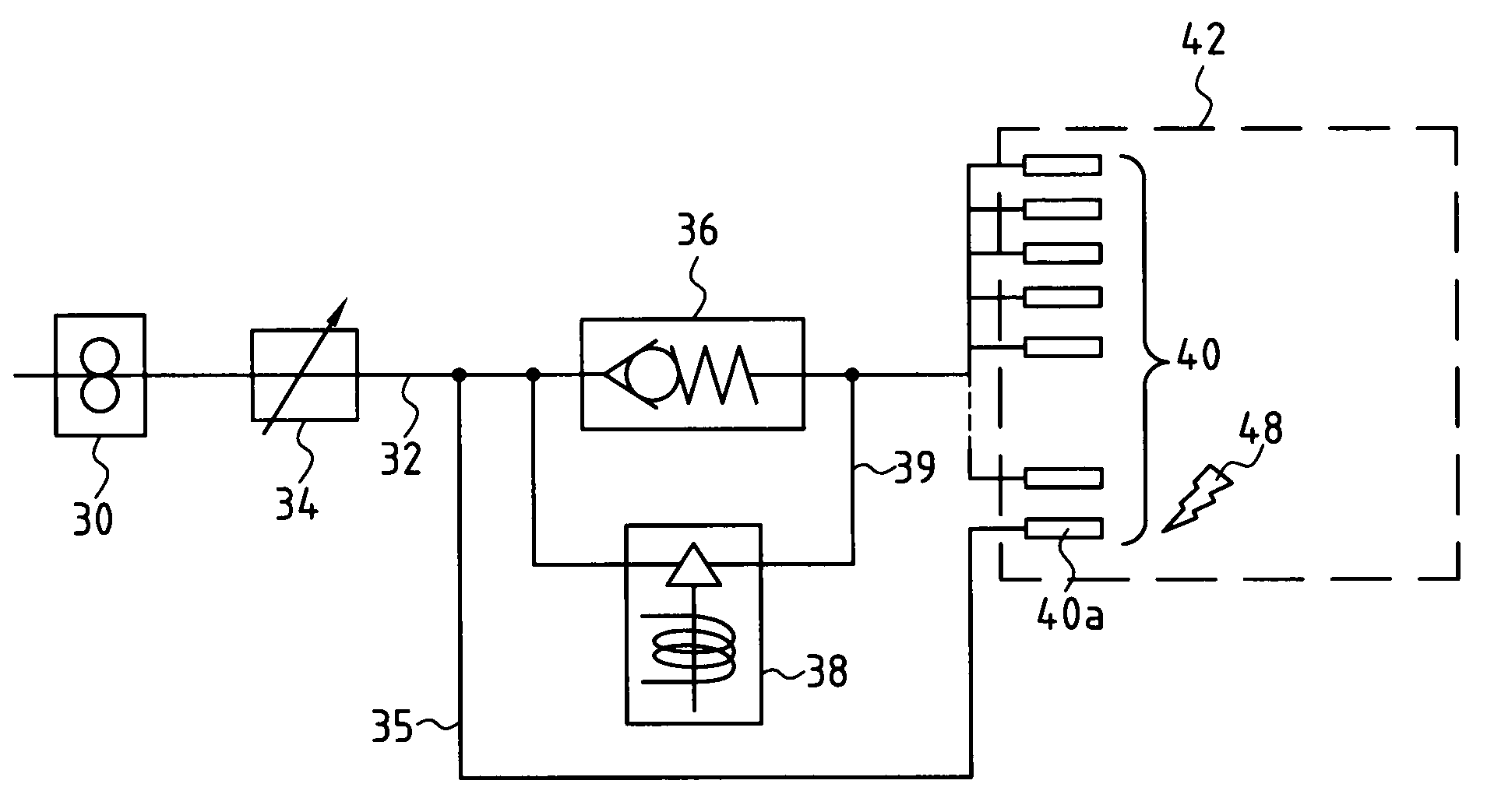
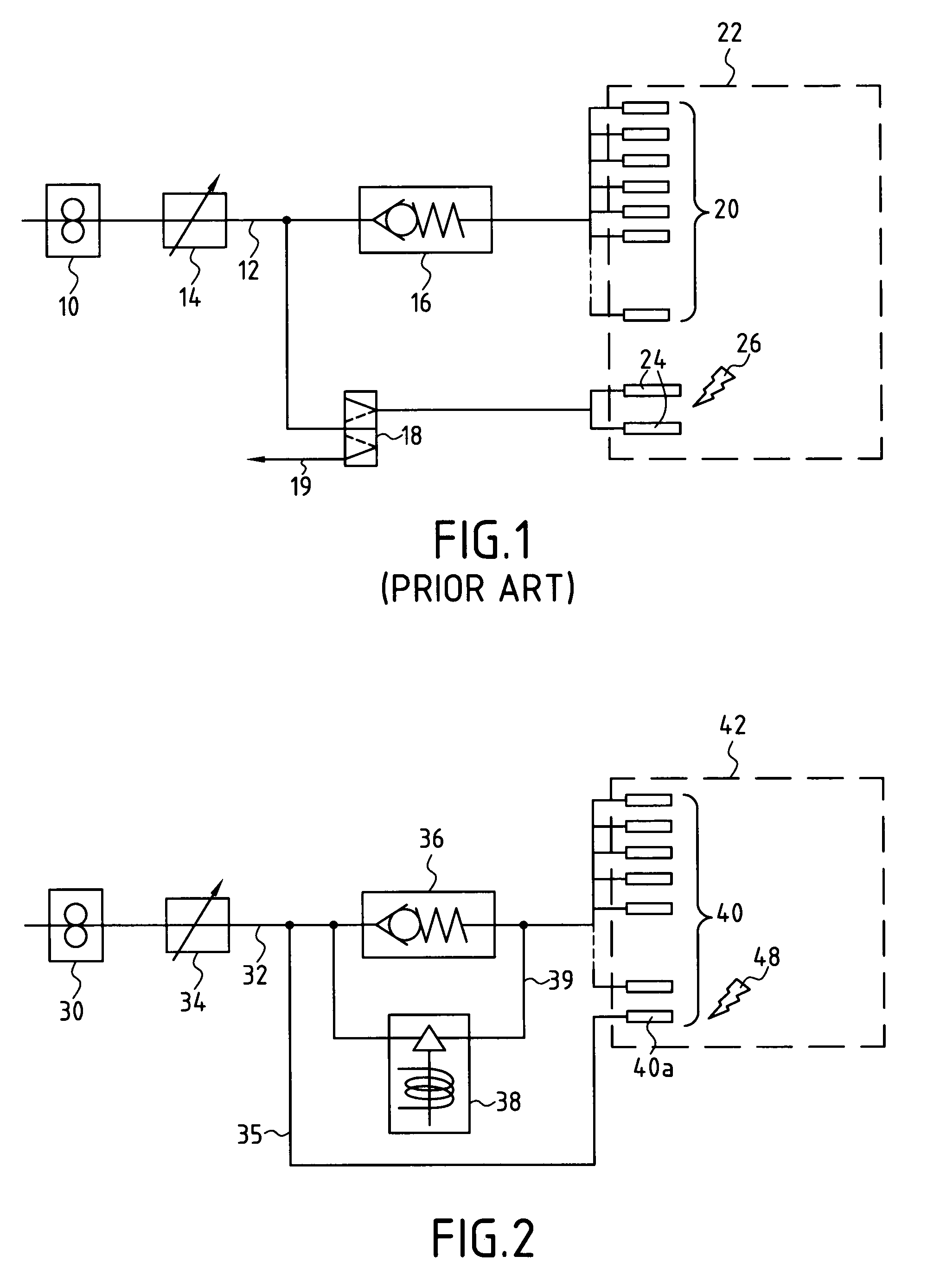
[0022]In the FIG. 2 fuel feed circuit, there can be seen, as in the circuit of FIG. 1, a pump 30 for taking fuel from a tank (not shown) to be delivered under pressure in a feed pipe 32 having a metering valve 34 mounted therein to control the fuel flow rate.

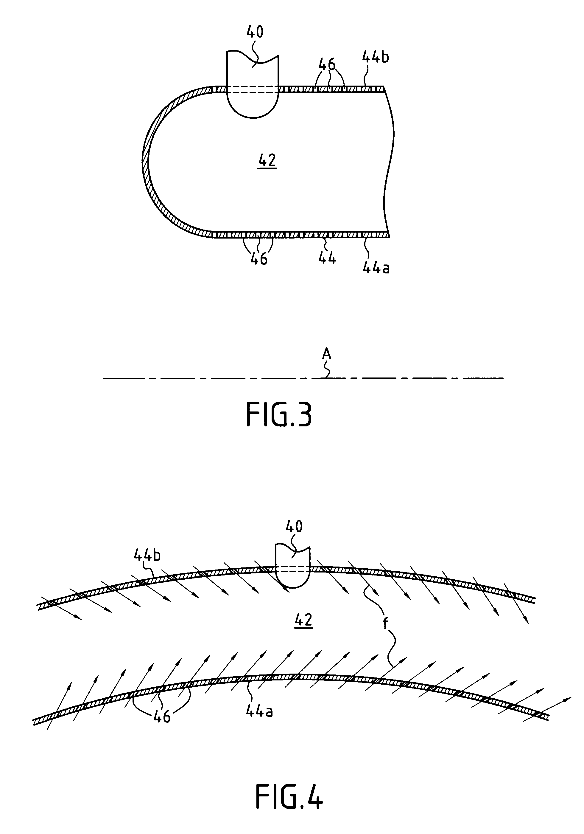
[0023]A plurality of main injectors 40 are mounted on a wall of a combustion chamber (represented by 42) to inject an air and fuel mixture into the combustion chamber. One 40a of the main injectors 40 is connected directly to the feed pipe 32 via a pipe 35. The other main injectors are connected to the feed pipe 32 via a circuit that comprises in parallel both a rated retaining valve or level valve 36, and an on / off valve 38 mounted in a pipe 39 bypassing the level valve 36, the pipe 35 being connected to the feed pipe 32 upstream from the level valve 36. The level valve 36 imposes a preadjusted head loss, e.g. of 6 bars to 10 bars (0.6 MPa to 1 MPa), e.g. by means of a rating spring. The on / off valve 38 may be electrically cont...


PUM


Abstract

At least one of the main injectors of the engine, forming a starter main injector, is fed directly by the pressurized feed pipe, while a head loss is imposed between the pressurized feed pipe and the other main injectors. Ignition is caused to take place at the starter main injector, and after ignition, said head loss imposed between the feed pipe and the other main injectors is eliminated so that all of the main injectors are fed with fuel at substantially the same pressure, without any imposed head loss.

Description

BACKGROUND OF THE INVENTION[0001]The invention relates to gas turbine helicopter engines, and in particular to feeding fuel to such engines, and to a method of starting them.[0002]A known circuit that is commonly used for feeding fuel to the combustion chamber of a helicopter engine is shown diagrammatically in FIG. 1.[0003]Fuel is taken from a tank (not shown) by means of a pump 10 that delivers the fuel under pressure in a feed pipe 12 having a metering valve 14 mounted therein for adjusting flow rate. The pipe 12 is connected via a rated retaining valve 16, or level valve, to a set of main injectors 20 that serve to inject an air and fuel mixture into the combustion chamber (represented by 22). The level valve 16 imposes a head loss, e.g. of 6 bars to 10 bars (0.6 megapascals (MPa) to 1 MPa), which is adjusted, for example, by means of a rating spring. At a location upstream of the level valve 16, the pipe 12 is also connected to one or more starter injectors 24, generally two in...

Claims


Application Information

Patent Timeline
IPC IPC(8): F02C7/26F02C7/22
CPCF02C7/264F01D17/00
Inventor VERDIER, HUBERT
Owner TURBOMECA SA
Why Eureka
Try Eureka