Bicycle quick release structure

Inactive Publication Date: 2008-09-04
SHIMANO INC
View PDF11 Cites 30 Cited by
  • Summary
  • Abstract
  • Description
  • Claims
  • Application Information

AI Technical Summary

Benefits of technology

[0009]One object of the present invention is to provide a bicycle wheel securing

Problems solved by technology

However, while certain bicycle parts are designed to be permanently attached to the bicycle, other bicycle parts such as bicycle wheels need to be loosened and removed relatively often.
However, it can be difficult for some

Method used


Image

  • Bicycle quick release structure
  • Bicycle quick release structure
  • Bicycle quick release structure

Examples


Example

Second Embodiment

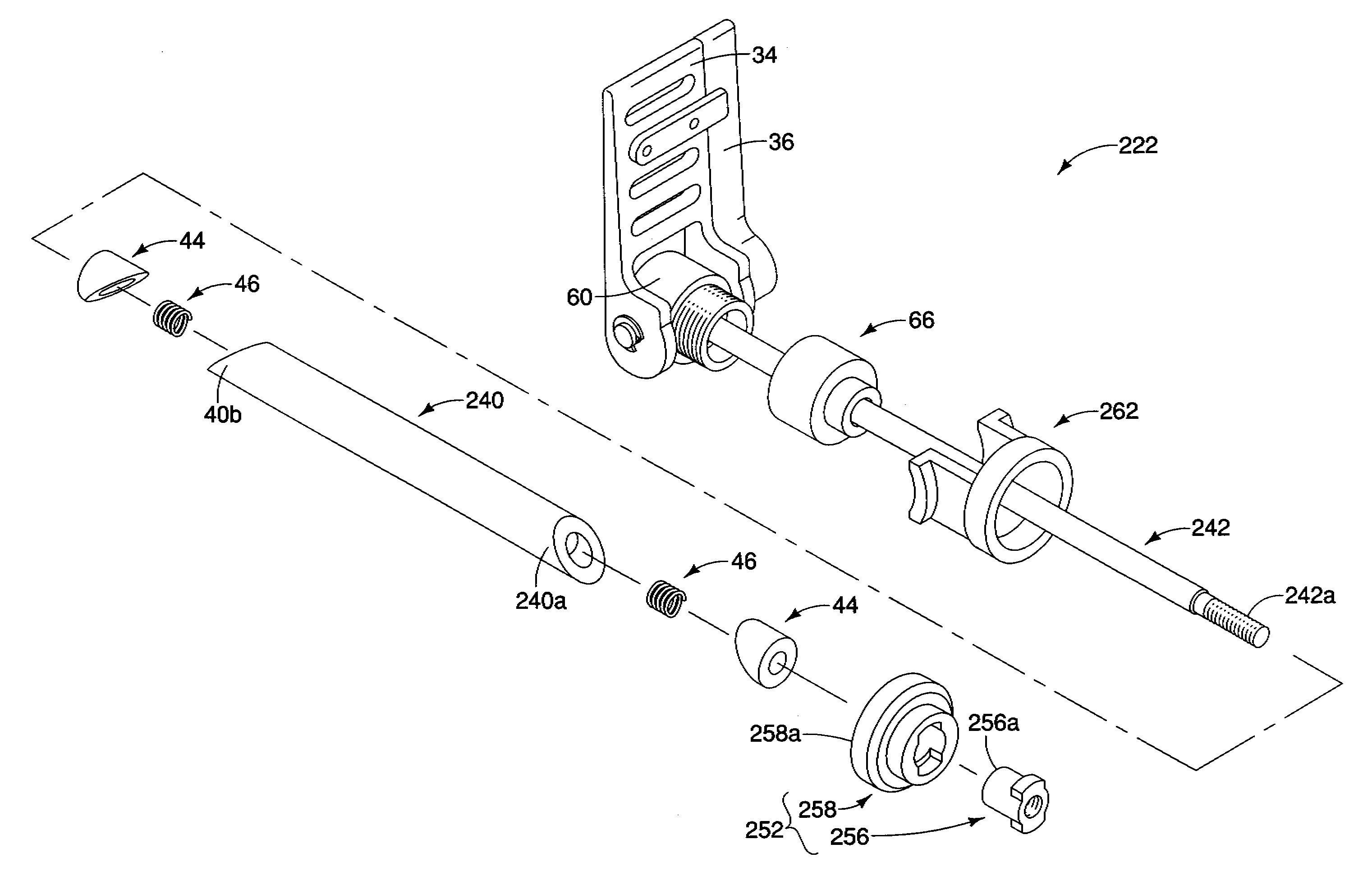
[0092]Referring now to FIGS. 20-35, a modified wheel securing axle 222 having a modified shaft member 230 with a modified first end portion 230a designed to be mounted to a modified rear triangle 213 in accordance with a second embodiment of the present invention will now be explained. The wheel securing axle 222 of this second embodiment is identical to the wheel securing axle 22 of the first embodiment, except for the first end portion 230a of the shaft member 230. Accordingly, this second embodiment will not be discussed and / or illustrated in detail herein, except as related to the first end portion 230a and the modified rear triangle 213. However, it will be apparent to those skilled in the bicycle art from this disclosure that the descriptions and illustrations of the first embodiment also apply to this second embodiment, except as explained and / or illustrated herein. Moreover, it will be apparent to those skilled in the bicycle art from this disclosure that t...

Example

[0093]Parts of this second embodiment that are identical to parts of the first embodiment will be identified with same reference characters as the first embodiment for the sake of convenience. Parts of this second embodiment that are functionally identical (but not exactly identical) to parts of the first embodiment will be identified with the same reference characters but with “200” added thereto for the sake of convenience.

[0094]The shaft member 230 includes a modified outer axle 240, a modified inner axle 242, an additional radial expansion part 44, an additional biasing member 46 and a retaining member 252. The modified rear triangle is identical to the rear triangle 13, except it includes a modified mounting flange 216 with an unthreaded through bore 216a. The outer axle 240 has a modified first axial end 240a that is identical to its second axial end 40b and a modified through bore 240d that is unthreaded. The inner axle 242 is longer than the inner axle 42 such that a modifie...

Example

Third Embodiment

[0096]Referring now to FIG. 36, a modified wheel securing axle 322 having a modified shaft member 330 with modified first and second end portions 330a and 330b designed to be mounted to a modified rear triangle 313 in accordance with a third embodiment of the present invention will now be explained. The wheel securing axle 322 of this third embodiment is identical to the wheel securing axle 22 of the first embodiment, except the modified shaft member 330. Accordingly, this third embodiment will not be discussed and / or illustrated in detail herein, except as related to the modified shaft member 330 and the modified rear triangle 313. However, it will be apparent to those skilled in the bicycle art from this disclosure that the descriptions and illustrations of the first embodiment also apply to this third embodiment, except as explained and / or illustrated herein. Moreover, it will be apparent to those skilled in the bicycle art from this disclosure that the wheel sec...


PUM


Abstract

A bicycle wheel securing structure includes a shaft member, a head member, a first wheel securing device, a second wheel securing device, a first lever member and a second lever member. The shaft member has first and second end portions and a longitudinal center axis. The head member is coupled at the second end portion. The first wheel securing device is positioned at the second end portion. The second wheel securing device positioned at at least one of the first and second end portions. The first lever member is operatively connected to the first wheel securing device to move the first wheel securing device in response to movement of the first lever member. The second lever member is operatively connected to the second wheel securing device to move the second wheel securing device in response to movement of the second lever member.

Description

BACKGROUND OF THE INVENTION[0001]1. Field of the Invention[0002]This invention generally relates to a bicycle wheel securing structure. More specifically, the present invention relates to a bicycle wheel securing structure, which utilizes a pair of wheel securing devices that are operated by a pair of lever members.[0003]2. Background Information[0004]Bicycling is becoming an increasingly more popular form of recreation as well as a means of transportation. Moreover, bicycling has become a very popular competitive sport for both amateurs and professionals. Whether the bicycle is used for recreation, transportation or competition, the bicycle industry is constantly improving the various components of the bicycle. One component that has been extensively redesigned is the bicycle wheel securing mechanism.[0005]In the past various bicycle parts have been attached using nut and bolt arrangements. However, while certain bicycle parts are designed to be permanently attached to the bicycle,...

Claims


Application Information

Patent Timeline
IPC IPC(8): B60B35/00
CPCB62K25/02Y10T403/7069Y10T403/7064B62K2206/00B60B27/026
Inventor TAKACHI, TAKESHI
Owner SHIMANO INC
Why Eureka
Try Eureka