Motor

a motor and axial direction technology, applied in the direction of electrical steering, motors, dynamo-electric components, etc., can solve the problem of difficulty in allowing the axial direction to reduce the dimensions of the motor

Inactive Publication Date: 2008-09-04
NIDEC CORP
View PDF16 Cites 31 Cited by
  • Summary
  • Abstract
  • Description
  • Claims
  • Application Information

AI Technical Summary

Problems solved by technology

However, according to the conventional motor, since a magnetic shield for minimizing the magnetic effect applied to a magnetic sensor by the stator is arranged between the stator and the magnetic sensor, it is difficult to allow the dimensions of the motor to be reduced in the axial direction.

Method used


Image

  • Motor
  • Motor
  • Motor

Examples


Embodiment Construction

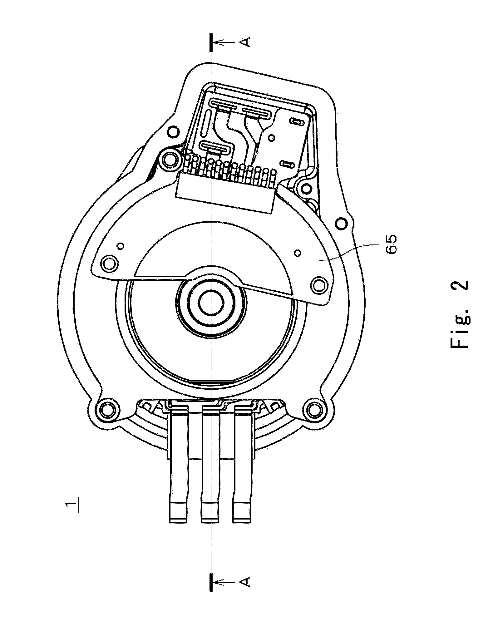
[0019]Note that in the description of preferred embodiments of the present invention herein, words such as upper, lower, left, right, upward, downward, top, and bottom for describing positional relationships between respective members and directions merely indicate positional and directions in the drawings. Such words do not indicate positional relationships and directions of the member mounted in an actual device. Also note that reference numerals, figure numbers, and supplementary descriptions are shown below for assisting the reader in finding corresponding components in the description of the preferred embodiments below to facilitate an understanding of the present invention. It is understood that these expressions in no way restrict the scope of the present invention.

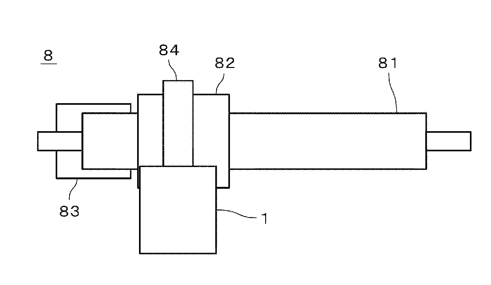
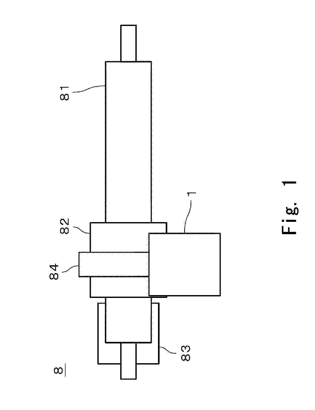
[0020]FIG. 1 is a schematic diagram of a power steering unit 8 (e.g., EPS (Electric Power Steering apparatus)) having a motor 1 according to a first preferred embodiment of the present invention. The power steering...


PUM


Abstract

A motor includes a housing having a substantially cylindrical shape accommodating therein a stator portion and a rotor portion. The housing includes a housing body having an opening at an upper side thereof, and a lid portion arranged between an armature and a sensor so as to close the opening of the housing body. Since the lid portion is made of a magnetic material and is arranged between the armature and the sensor, a magnetic effect on the sensor caused by a magnetic force generated at the armature is minimized. By virtue of such configuration in which the lid portion of the housing functions as a magnetic shield, the motor can be smaller in the axial direction compared with a configuration in which an extra layer of magnetic shield is arranged.

Description

FIELD OF THE INVENTION [0001]The present invention relates to a motor.DESCRIPTION OF THE RELATED ART [0002]Conventionally, a hydraulic power steering apparatus is used in a vehicle such as a passenger car or the like to assist an operator in maneuvering the vehicle. The hydraulic power steering apparatus uses a pump operated by an engine of the vehicle to generate force to assist the operator's steering. In recent years, an electric power steering apparatus which uses a motor operated by a vehicle battery has become available. Such a system is more power efficient than the conventional hydraulic power steering apparatus.[0003]Conventionally, the motor used to drive the electric power steering apparatus may include a magnetic sensor and a permanent magnet which is used to detect a rotary position of a rotor relative to a stator.[0004]Also conventionally, the motor used to drive the electric power steering may include a substantially cylindrical shape having a cylindrical stator and a...

Claims


Application Information

Patent Timeline
Patent Type & Authority Applications(United States)
IPC IPC(8): B62D5/04H02K11/00H02K5/04
CPCB62D5/0403H02K11/0021H02K11/0005H02K11/215H02K11/0141
Inventor KATAOKA, NAKABAMIGITA, TAKAYUKIHAGA, HIDEHIRO
Owner NIDEC CORP
Why Eureka
Try Eureka