Vertical Axis Windmill And Wind Turbine System For Generating Electricity From Wind Energy

a technology of wind turbines and wind turbines, which is applied in the direction of wind motors with perpendicular air flow, non-positive displacement fluid engines, liquid fuel engine components, etc., can solve the problems of limiting the power generation capabilities of wind turbines, the speed of the blade tip can exceed the wind speed, and the rotation of the wind turbine is limited, so as to achieve continuous rotation, efficient electricity generation, and the effect of reducing the pivoting movement of the rear portion

Inactive Publication Date: 2008-09-04
SEABELL INT CO LTD
View PDF0 Cites 47 Cited by
  • Summary
  • Abstract
  • Description
  • Claims
  • Application Information

AI Technical Summary

Benefits of technology

[0020]In other embodiments, the stopper is arranged to dampen the pivoting movement of the rear portion.
[0021]Thus, this wind turbine design can be effective in a situation where the TSR is below 1 or above 1.
[0022]It is a primary objective of the present invention to provide a wind turbine where, relative to the wind speed, the rotation moment due to lift from front wind currents, and the rotation moment due to drag from rear or diagonally rear wind currents can both be generated. Thus, in an environment where wind speed and the wind direction are constantly changing, the wind turbine can continuously rotate and efficiently generate electricity.
[0023]It is another objective of the present invention to provide a simplistic design of small to medium size that can be produced at relatively low cost using low or easy maintenance components.
[0024]It is also an objective of the present invention to provide a low-cost electricity generation solution that can be installed anywhere with relative ease and can be applied to homes, schools, factories, offices, and remote locations that have high electricity delivery costs such as parks, meadows, ravines and islands.

Problems solved by technology

Thus, wind turbine rotation is limited since the blade speed is limited to wind speed thereby limiting the electricity generation capabilities of the wind turbine.
For vertical axis lift type wind turbines, however, the speed of a tip of a blade can exceed wind speed.
At these speeds, the wind turbine can generate a high level of electricity, but the aerodynamics of the blades are usually inefficient when blade speed is below wind speed, i.e. when TSR<1.
Thus, a vertical axis lift wind turbine only generates substantial amounts of electricity when TSR>1. Moreover, in low wind speed environments, blade aerodynamics are inefficient and cannot produce enough torque to initiate rotation, and the wind turbine usually requires a separate power source to initiate rotation.
However, adding components like that of the Savonius design increases the number of parts, raises production costs and increases design complexity.
Moreover, in high wind speed environments, the added components cause drag and resistance to the rotation of the wind turbine, lowering the efficiency of the wind turbine.
Although this arrangement creates enough start up torque by generating drag in low wind speeds, in high wind speeds the same concaved curves produce vortexes that lower wind turbine efficiency.
Additionally, especially if the wind turbine is susceptible to rain or moisture, the springs necessary for the system to support the angle of the blade in relation to the shaft can deteriorate and break.
Since it has no concaved curve like that of a Savonius design, there still exists the issue of inadequate torque to initiate rotation prior to TSR reaching 1.
As discussed above, in a drag type vertical axis wind turbine, wind turbine rotation is limited to TSR=1, limiting electricity generation.
When TSR>1, lift type vertical axis wind turbines are efficient, but when the TSR<1, the aerodynamics are inefficient and the aerodynamics are inadequate to produce enough startup torque to initiate wind turbine rotation, necessitating a secondary power source to begin rotation.

Method used


Image

  • Vertical Axis Windmill And Wind Turbine System For Generating Electricity From Wind Energy
  • Vertical Axis Windmill And Wind Turbine System For Generating Electricity From Wind Energy
  • Vertical Axis Windmill And Wind Turbine System For Generating Electricity From Wind Energy

Examples


Embodiment Construction

[0041]Like drawing numbers on different figures identify identical or functionally similar structural features of the invention. The invention is not limited to the particular methodology, materials and modifications described and as such may, of course, vary. The terminology used herein is for the purpose of describing particular aspects only, and is not intended to limit the scope of the present invention, which is limited only by the appended claims.

[0042]Unless defined otherwise, all technical and scientific terms used herein have the same meaning as commonly understood to one of ordinary skill in the art to which this invention belongs.

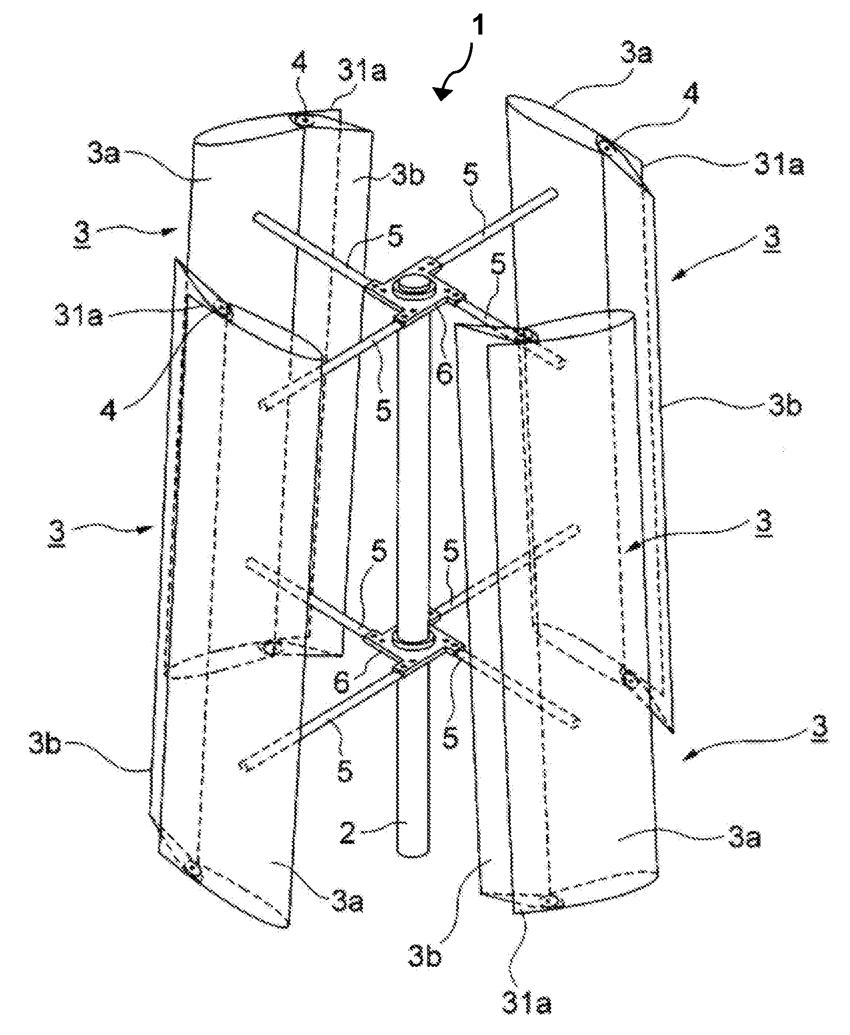
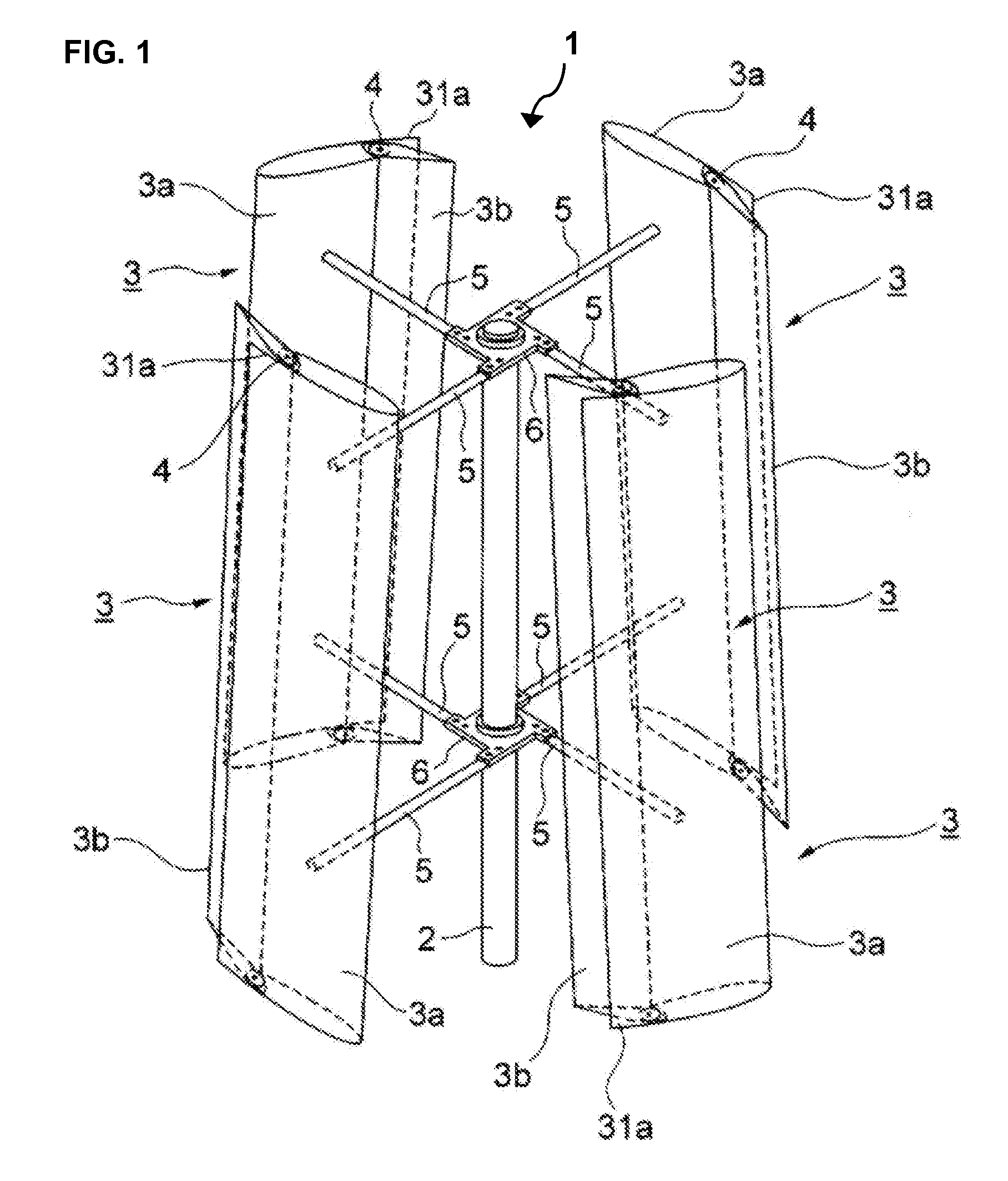
[0043]FIG. 1 depicts the overall structure of wind turbine 1, which is a wind turbine in accordance with the present invention. Wind turbine 1 is shown arranged with a substantially vertical rotating shaft 2 fixedly secured to four blades 3. Blades 3 include front portions or front blades 3a and rear portions or rear blades 3b. Front portions 3a ...


PUM


Abstract

A lift-type wind turbine having a substantially vertical rotating shaft and a plurality of substantially vertical blades secured to the shaft. Each blade includes a front portion, a rear portion, and a pivot axis pivotally securing the rear and front portions. The rear portion pivots relative the front portion. The blades additionally include bottom and top edges positioned on each of the front portions. Each bottom edge is arranged substantially equidistant from the shaft proximate a first circumference extending substantially horizontally about the shaft, whereas each top edge is arranged substantially equidistant from the shaft proximate a second circumference extending substantially horizontally about the shaft. The blades are angled relative to the rotating shaft. The blades have an open, drag means position as well as a closed, lift means position, and passively switch between the positions based on wind speed for efficient rotation.

Description

CROSS REFERENCE TO RELATED APPLICATIONS[0001]This application claims priority to U.S. Provisional Application No. 60 / 940,744, filed May 30, 2007, which is incorporated herein by reference, and this application claims priority to Japanese Patent Application No. 2007-146851, filed Jan. 10, 2007.FIELD OF THE INVENTION[0002]The invention is related to wind turbine systems and windmills that utilize improved blade designs, specifically to vertical axis wind turbines.BACKGROUND OF THE INVENTION[0003]Windmill and wind turbine systems are generally either horizontal axis systems where the rotating shaft is arranged in a horizontal direction, or vertical axis where the rotating shaft is arranged in a vertical direction.[0004]Vertical axis wind turbines rotate in the same position irrespective of wind direction whereas horizontal axis wind turbines must be positioned to face the wind direction in order to rotate. Vertical axis wind turbines also rotate with relatively silent movement and fit ...

Claims


Application Information

Patent Timeline
Patent Type & Authority Applications(United States)
IPC IPC(8): F03D3/02
CPCF03D3/067F03D7/06Y02E10/74F05B2240/31F05B2260/75F05B2240/214Y02P70/50
Inventor UNNO, YUJI
Owner SEABELL INT CO LTD
Why Eureka
Try Eureka