In-Process Non-Contact Measuring Systems and Methods for Automated Lapping Systems

a non-contact, measuring system technology, applied in the field of measurement systems, can solve the problems of additional surface polishing and damage to the surface, and achieve the effects of reducing costs, reducing time efficiency and quality, and reducing the undesirable characteristics of prior measuring devices

Inactive Publication Date: 2008-09-11
THE BOEING CO
View PDF10 Cites 13 Cited by
  • Summary
  • Abstract
  • Description
  • Claims
  • Application Information

AI Technical Summary

Benefits of technology

[0004]Embodiments of measuring systems and methods for automated lapping systems in accordance with the disclosure are configured to mitigate the undesirable characteristics of prior measuring devices for an injection mold in an automatic lapping system described above. Thus

Problems solved by technology

When the diamond tips were removed from the surface, the surface may be either damaged or

Method used


Image

  • In-Process Non-Contact Measuring Systems and Methods for Automated Lapping Systems
  • In-Process Non-Contact Measuring Systems and Methods for Automated Lapping Systems
  • In-Process Non-Contact Measuring Systems and Methods for Automated Lapping Systems

Examples


Embodiment Construction

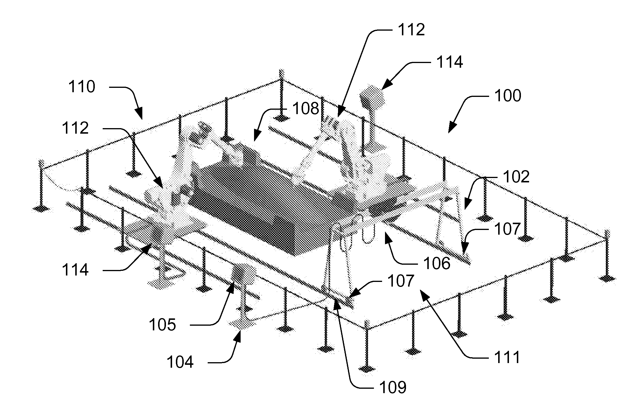
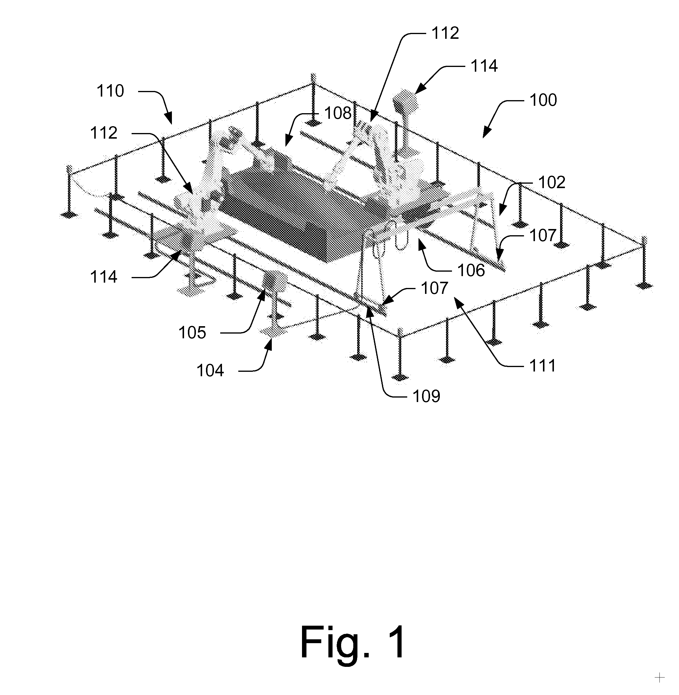
[0014]Embodiments of the present invention relate to measuring systems and methods for automated lapping systems. Many specific details of certain embodiments of the invention are set forth in the following description and in FIGS. 1-4 to provide a thorough understanding of such embodiments. One skilled in the art, however, will understand that the present invention may have additional embodiments, or that the present invention may be practiced without several of the details described in the following description.

[0015]FIG. 1 illustrates an example of an in-process non-contact measuring system 100 in accordance with an embodiment of the present invention. The system 100 includes a moveable frame 102, a control component 104, and a non-contact measuring device 106 to measure a surface of a lapped work product 108 and transmit measurement data of the surface of the lapped work product 108 to the control component 104. In this example, the moveable frame 102 can be incorporated into an...


PUM


Abstract

In-process non-contact measurement systems and methods for automated lapping systems are disclosed. In an embodiment, a moveable frame can be controllably positioned proximate to a lapped work product. A control component can provide first control signals to control a movement of the moveable frame relative to the lapped work product. A non-contact measuring device can be coupled to the moveable frame measures a surface of the lapped work product and can transmit measurement data of the surface of the lapped work product to the control component. The control component can further provide second control signals to control a movement of the non-contact measuring device relative to the moveable frame.

Description

FIELD OF THE INVENTION[0001]The present disclosure generally relates to measurement systems, and more specifically to in-process non-contact measurement systems and methods for automated lapping systems.BACKGROUND OF THE INVENTION[0002]Acquiring high quality polished and lapped injection molds requires exacting surface finish and surface form. Surface finish is quantified visually, however, surface form must be measured. Historically, injection molds were measured using hand-held gauging devices. The gauging devices scanned the surface of the injection mold by remaining in contact with rounded diamond tips that were directly in contact with the surface of the injection mold. When the diamond tips were removed from the surface, the surface may be either damaged or may require additional surface polishing of the injection mold to remove any contact paths.[0003]The present state of the measuring art requires significant downtime of the automated lapping system, hence, the measurement p...

Claims


Application Information

Patent Timeline
IPC IPC(8): G01B3/14
CPCB24B19/26G01B21/20B24B37/00B24B35/005
Inventor WOOD, JEFFREY H.BERKEL, THOMAS R.BENDER, ROBERT E.
Owner THE BOEING CO
Why Eureka
Try Eureka