Unconventional integrated propulsion systems and methods for blended wing body aircraft

a technology of integrated propulsion and blended aircraft, which is applied in the field of aircraft propulsion, can solve the problems of affecting the operability of the engine, the sensitivity of the boundary layer the low loss integration of the engine on the airframe is more difficult, so as to improve the weight and balance characteristics, and reduce the sensitivity to flow distortion and ingestion

Inactive Publication Date: 2010-02-23
THE BOEING CO
View PDF21 Cites 72 Cited by
  • Summary
  • Abstract
  • Description
  • Claims
  • Application Information

AI Technical Summary

Benefits of technology

[0005]Embodiments of integrated propulsion systems and methods for blended wing body aircraft in accordance with the present invention are configured to mitigate the undesirable characteristics of the prior art described above. Thus, embodiments of systems and methods in accordance with the present invention may advantageously provide improved weight and balance characteristics, reduced sensitivity to flow distortion and boundary layer ingestion, and improved propulsion system performance in comparison with the prior art.

Problems solved by technology

For example, as the bypass ratio of the engines of the BWB aircraft 50 is increased, the engines and nacelles 56 get bigger and heavier, which makes a low loss integration of the engines on the airframe more difficult, and which also adversely affects the weight and balance of the BWB aircraft 50.
Passing that portion of the boundary layer flow through the engines can improve the overall efficiency, however, a key concern of this approach is pressure distortion in the flow at the engine face (both the fan and core streams) and its resulting impact on engine operability.

Method used


Image

  • Unconventional integrated propulsion systems and methods for blended wing body aircraft
  • Unconventional integrated propulsion systems and methods for blended wing body aircraft
  • Unconventional integrated propulsion systems and methods for blended wing body aircraft

Examples


Embodiment Construction

[0017]The present invention relates to integrated propulsion systems and methods for blended wing body (BWB) aircraft. Many specific details of certain embodiments of the invention are set forth in the following description and in FIGS. 2-8 to provide a thorough understanding of such embodiments. One skilled in the art, however, will understand that the present invention may have additional embodiments, or that the present invention may be practiced without several of the details described in the following description.

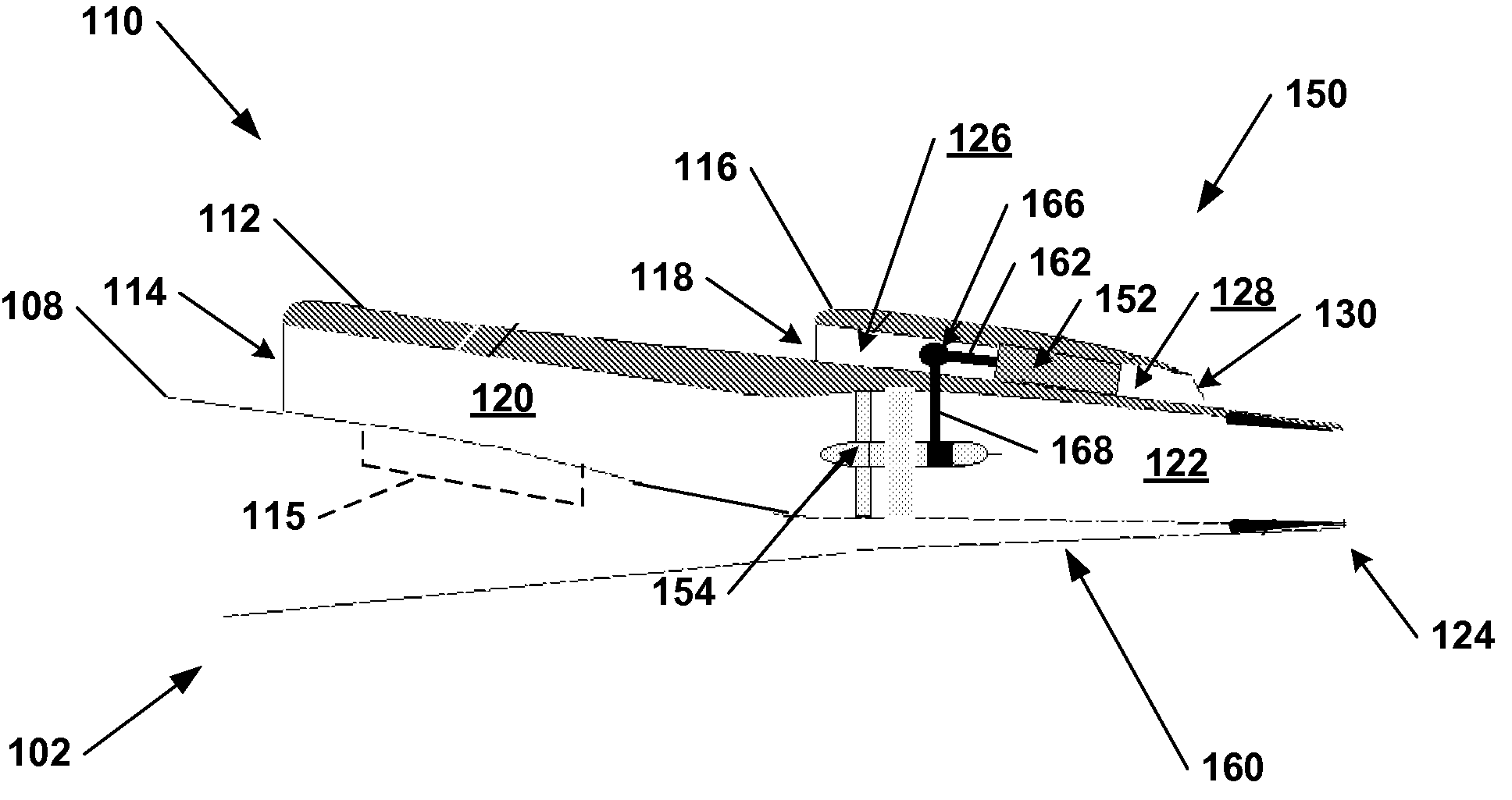
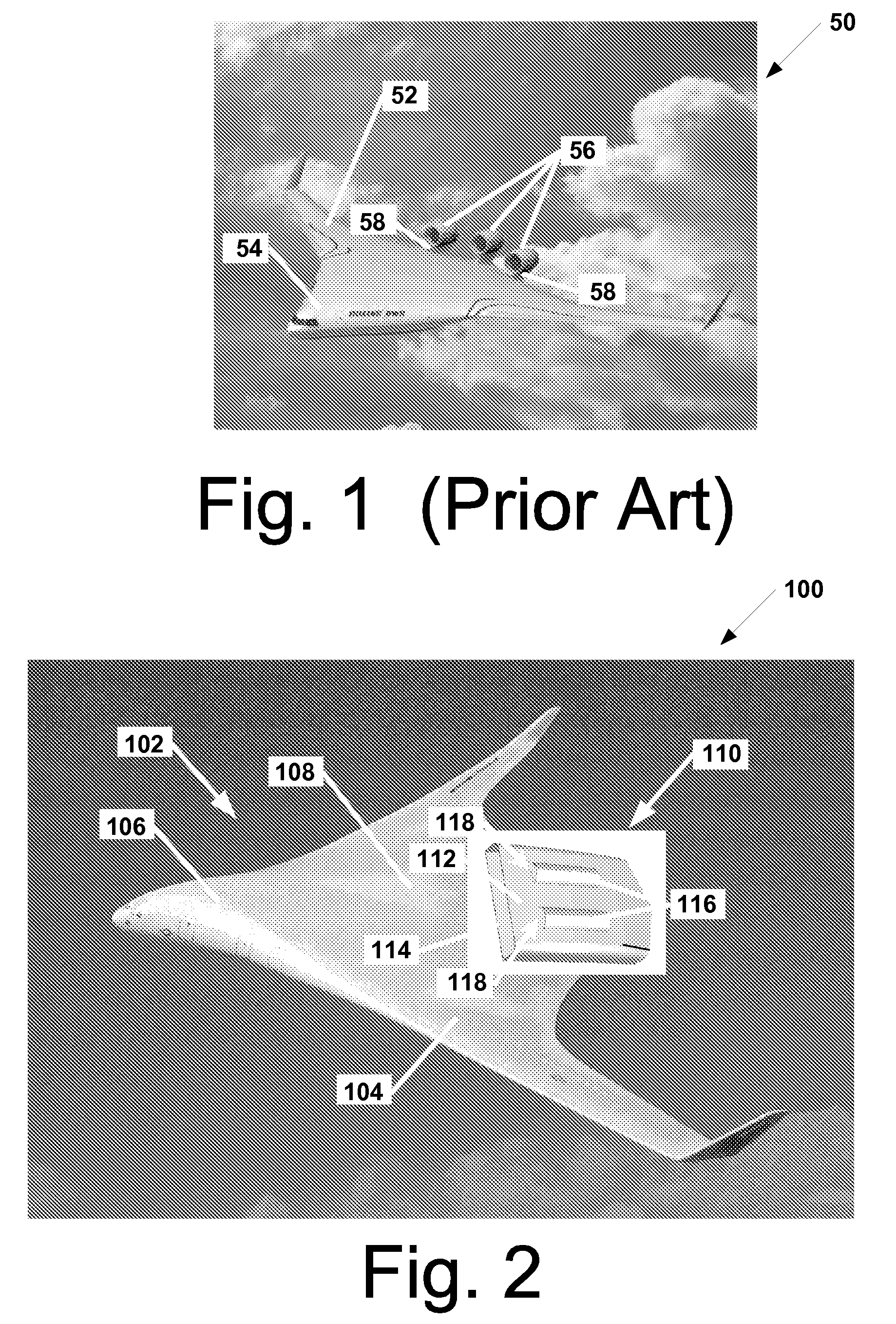
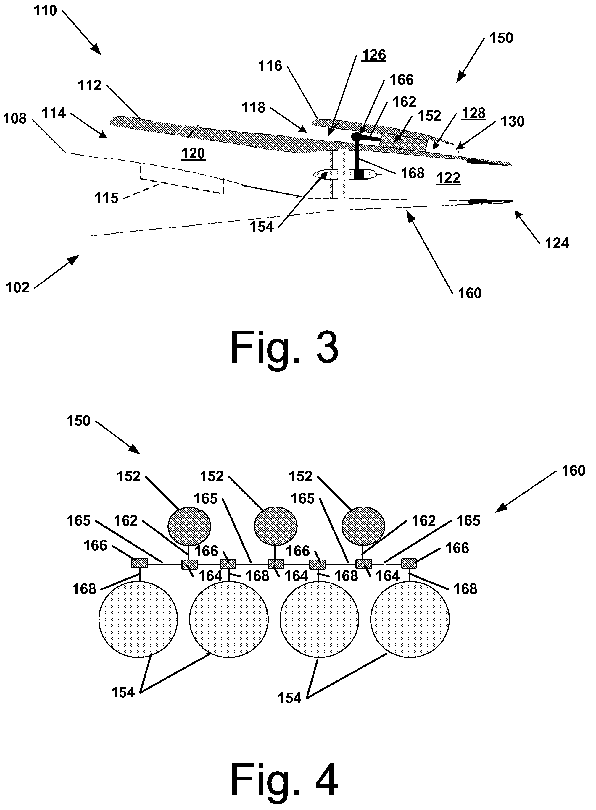
[0018]FIG. 2 is an isometric view of a blended wing body aircraft 100 in accordance with an embodiment of the present invention. In this embodiment, the BWB aircraft 100 includes an airframe 102 having blended wing and body portions 104, 106, and an integrated propulsion system 110 disposed on an upper surface 108 of the airframe 102. The integrated propulsion system 110 provides propulsion power for the BWB aircraft 100. As described more fully below, the integrated p...


PUM


Abstract

Integrated propulsion systems and methods for blended wing aircraft are disclosed. In one embodiment, a propulsion system at least one engine operatively disposed within an engine flow duct having an engine inlet and an engine exhaust aperture, and at least one fan operatively disposed within a fan flow duct having a fan inlet and a fan exhaust aperture. The engine and fan rotational axes extending at least approximately along a lengthwise direction of the aircraft, the fan flow duct being separate from the engine flow duct. A transmission assembly is operatively coupled between the at least one engine and the at least one fan, the transmission assembly being configured to transmit a rotary output from the at least one engine to rotate the at least one fan.

Description

FIELD OF THE INVENTION[0001]The present invention generally relates to aircraft propulsion, and more specifically, to integrated propulsion systems and methods for blended wing body aircraft.BACKGROUND OF THE INVENTION[0002]Blended wing body (BWB) aircraft are being studied by governmental agencies, universities, and private industry for various applications, including passenger and cargo carrying applications. A BWB may be characterized as a hybrid shape that primarily resembles a flying wing, but also incorporates some features of a conventional aircraft. For example, FIG. 1 shows a conventional BWB aircraft concept 50 in accordance with the prior art. The BWB aircraft 50 includes an efficient, high-lift wing assembly 52, and a central, airfoil-shaped body 54. In the concept shown in FIG. 1, the BWB aircraft 50 includes three engines located in nacelles 56 mounted above the upper surface on pylons 58 near a trailing edge of the BWB aircraft 50. It is desirable to have engines with...

Claims


Application Information

Patent Timeline
Patent Type & Authority Patents(United States)
IPC IPC(8): B64C15/02
CPCB64C15/02B64D27/14B64D35/00B64C2039/105Y02T50/12Y02T50/44Y02T50/10Y02T50/40
Inventor MCCOMB, JAMES G.
Owner THE BOEING CO
Why Eureka
Try Eureka