Positioning Device For Window Frame

a technology for window frames and positioning devices, applied in mechanical devices, springs/dampers, shock absorbers, etc., can solve the problems achieve the effect of saving a lot of labor

Inactive Publication Date: 2008-09-11
HUNG TIAN TSZ
View PDF35 Cites 5 Cited by
  • Summary
  • Abstract
  • Description
  • Claims
  • Application Information

AI Technical Summary

Benefits of technology

[0009]In installing the window frame, the positioning devices in accordance with the present invention are placed at two sides of a bottom of the window frame, in which the bottom board of the positioning device contacts with a cement wall, and the upper board contacts with the bottom of the window frame. Then a horizontal detection device is placed on the frame for aiding to adjust the horizontal position of the window frame. During the adjustment, along with the use of the horizontal detection device, the lifting tube can be moved up and down until the window frame becomes a horizontal state, and then the screw is screwed into the fixing hole to fasten the lifting tube onto the seat such that a portion of the lifting tube is exposed from a top of the seat. Furthermore, the present invention is provided with an elastic member, which acts as a cushion, between the bottom board and the upper board. With the elastic member, there is no need to hold the window frame with a certain weight when performing the horizontal position adjustment, which saves a lot of labor. Besides applied on the window frame, the present invention also can be applied to adjust a doorframe or a machine tool to a horizontal state or a predetermined angled state. Accordingly, the present invention can be used more widely.

Problems solved by technology

With the elastic member, there is no need to hold the window frame with a certain weight when performing the horizontal position adjustment, which saves a lot of labor.

Method used


Image

  • Positioning Device For Window Frame
  • Positioning Device For Window Frame
  • Positioning Device For Window Frame

Examples


Embodiment Construction

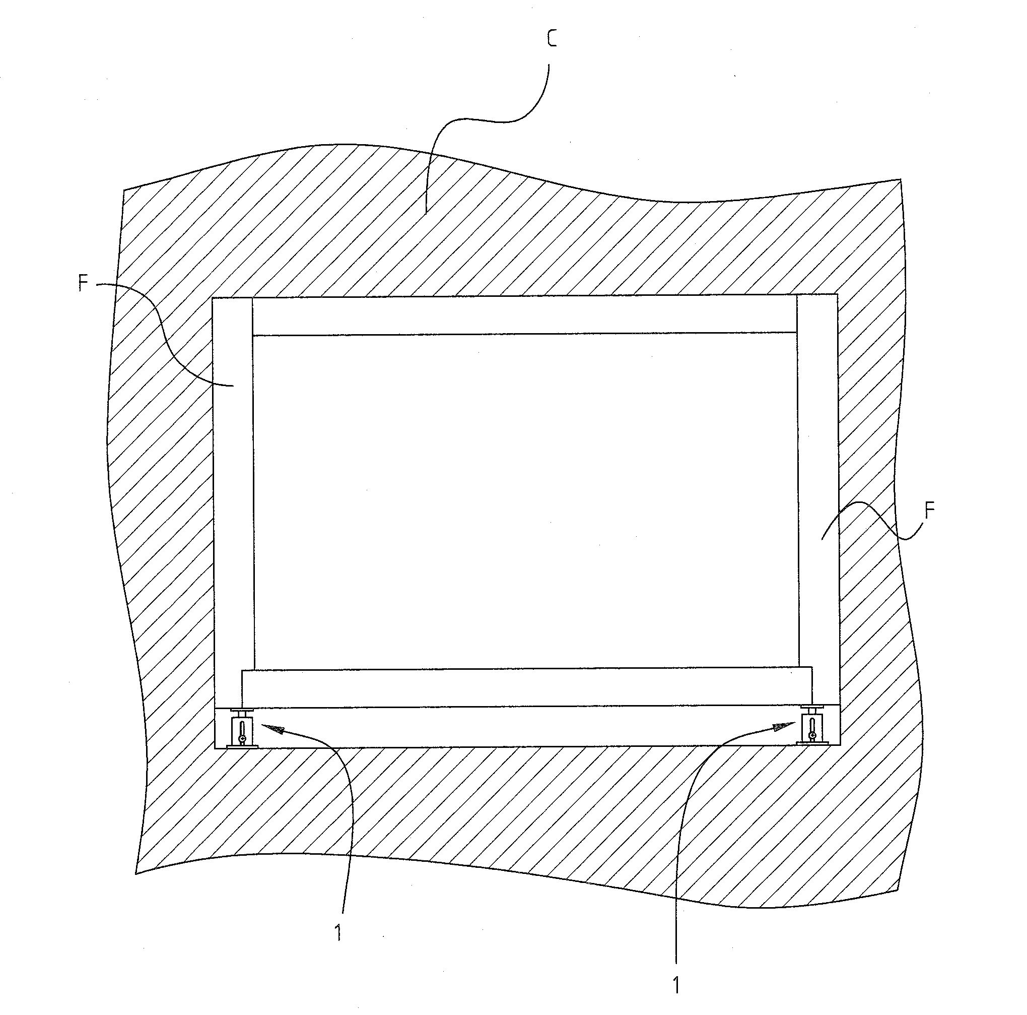
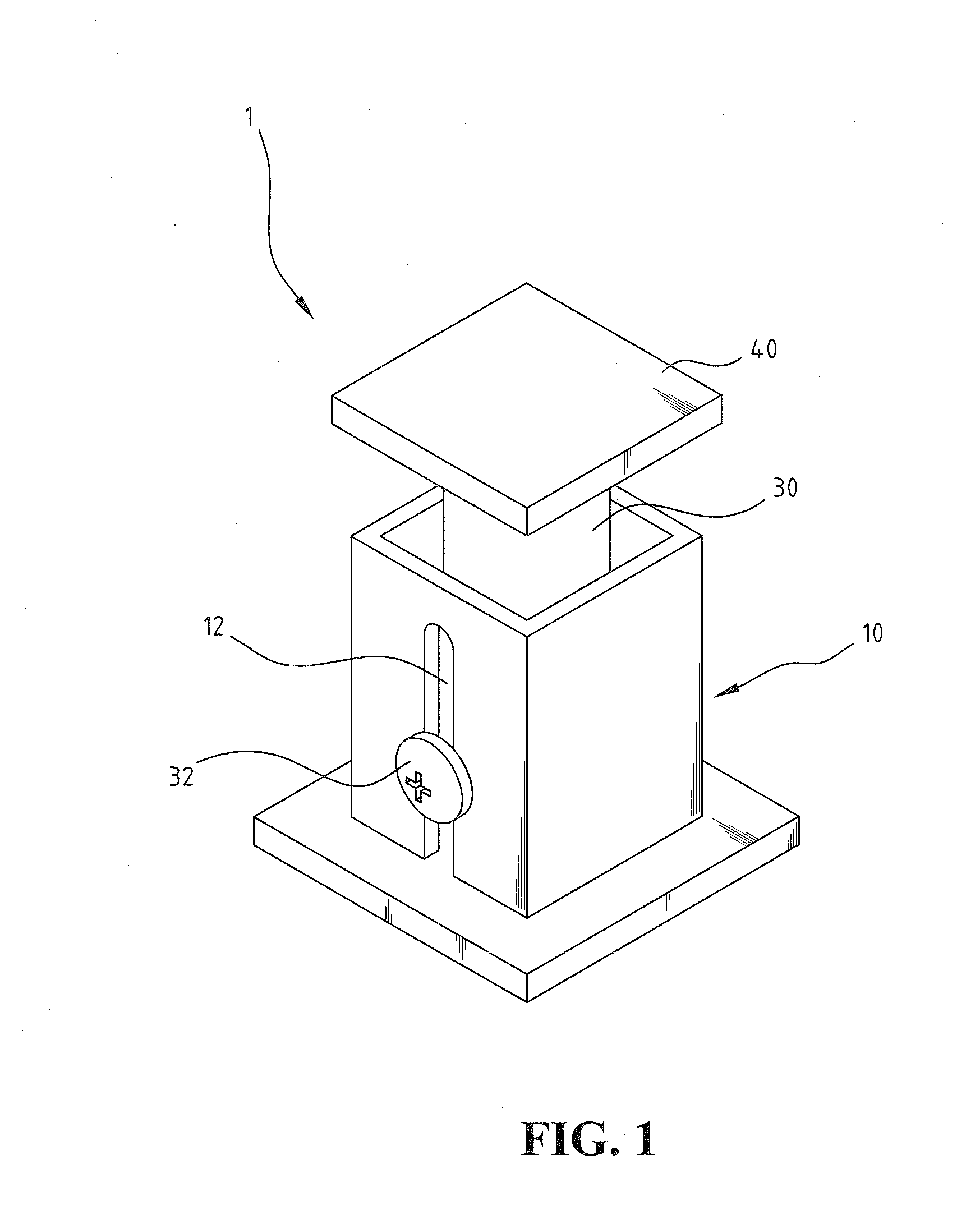
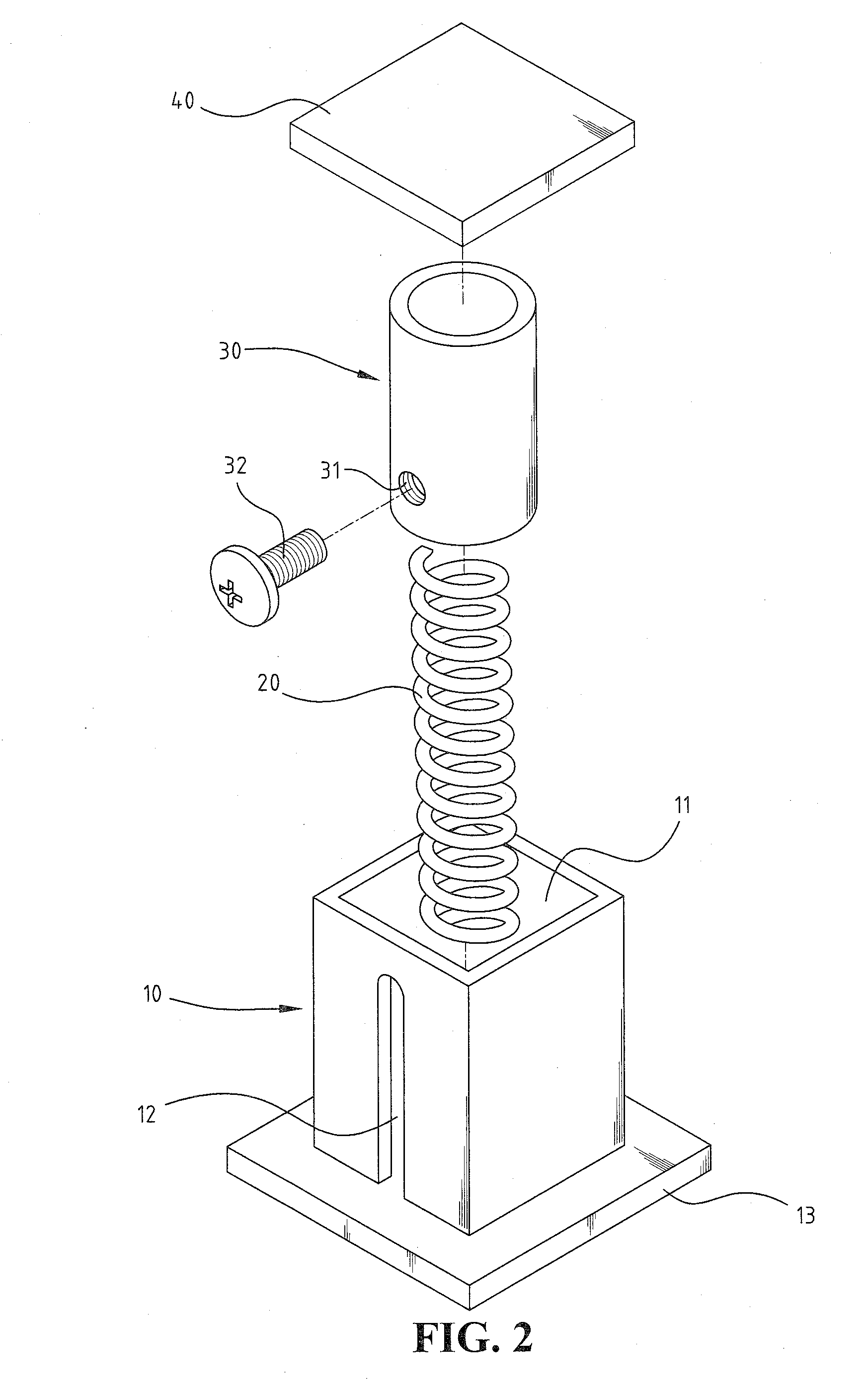
[0018]Referring to FIGS. 1 and 2, a positioning device 1 for a window frame in accordance with an embodiment of the present invention comprises a seat 10, an elastic member 20, a lifting tube 30 and an upper board 40. The lifting tube 30 is received in the seat 10 and fastened onto the seat 10 by a screw 32, and a portion of the lifting tube 30 is exposed from a top of the seat 10, whereby the positioning device 1 can be placed under the window frame to perform its horizontal position adjustment.

[0019]With reference to FIG. 1, the seat 10 in this embodiment is, but not limited to, a square tubular shape. It may be a round tube or other shapes of tubes. The seat 10 has a chamber 11 defined therein for receiving the elastic member 20 and the lifting tube 30. A limit slot 12 is longitudinally defined on a side wall of the seat 10. A width of the limit slot 12 is designed to fit with a diameter of a threaded portion of a screw 32, so that the threaded portion of the screw 32 can pass th...


PUM


Abstract

A positioning device for adjusting a horizontal position of a window frame is disclosed herein, which includes a tube-shaped seat having a chamber defined therein and a limit slot formed on a side wall thereof; a lifting tube, in which an end of the lifting tube is received in the chamber of the seat, a screw is inserted through the limit slot and screwed into a fixing hole on a side wall of the lifting tube, whereby the lifting tube can be fastened on the seat, and a portion of the lifting tube is exposed from a top of the seat; an upper board mounted on the other end of the lifting tube; and an elastic member sleeved into the lifting tube and having both ends respectively pressed against the seat and the upper board.

Description

BACKGROUND OF THE INVENTION[0001]1. Field of the Invention[0002]The present invention generally relates to a positioning device, and in particular to a positioning device for adjusting a horizontal position of a window frame.[0003]2. The Prior Arts[0004]Generally, when installing an aluminum window, a window frame must be firstly mounted in an opening on a cement wall. Due to the requirement of a waterproofing work that has to be performed around the aluminum window, the opening is usually bigger than the window frame. After the window frame is installed, the gap around the window frame is filled up.[0005]When performing the aforementioned window frame installment, the horizontal state of the window frame must be considered in order to prevent the window from automatically sliding after the window is mounted in the frame. As an example commonly adopted in the prior art, a large gap under the bottom of the window frame is reserved for adjusting the horizontal position of the window f...

Claims


Application Information

Patent Timeline
Patent Type & Authority Applications(United States)
IPC IPC(8): E04F21/00
CPCE06B1/6069
Inventor HUNG, TIAN-TSZ
Owner HUNG TIAN TSZ
Why Eureka
Try Eureka