Process of Manufacturing Low-Profile Connector

a technology of low-profile connectors and manufacturing processes, which is applied in the direction of metal material coating processes, liquid/solution decomposition chemical coatings, coatings, etc., can solve the problems of complex processing procedures, consuming a large amount of time and labor, and reducing the research cost of the researcher, so as to save time and labor, simplify processing procedures, and reduce the effect of cost reduction

Inactive Publication Date: 2011-03-31
CHOU CHIH YEH
View PDF2 Cites 0 Cited by
  • Summary
  • Abstract
  • Description
  • Claims
  • Application Information

AI Technical Summary

Benefits of technology

[0010]It is therefore a primary object of the present invention to provide an improved process of manufacturing low-profile connector, in order to eliminate the problems with the conventional ways for manufacturing a low-profile connector.
[0012](a) Forming connector main body: Two connector main bodies for low-profile connector and a holding support are integrally formed using a plastic material through injection molding; the two connector main bodies are symmetrically formed on two opposite sides of the holding support, and each have a forward projected plug end, at where the connector main bodies are connected to the edges of the two opposite sides of the holding support; the joints of the connector main bodies and the holding support have a relatively smaller thickness to facilitate subsequent separation of finished connector main bodies from the holding support; on a front side of the plug end of each of the connector main bodies, there are formed a plurality of pins, which are parallelly arranged side by side; and the connector main bodies each have a rear side formed into a flat face;
[0016]The connector main body for low-profile connector manufactured according to the process of the present invention includes integrally formed pin terminals to effectively reduce the costs for researching and developing production engineering and making molds, to simplify processing procedures and save a lot of time and labors that are otherwise needed to process metal pins and separated half shells, and to effectively reduce the stock of components and save the warehousing management cost. Moreover, the present invention provides simplified and automated manufacturing process to omit manual assembling and accordingly, save labor cost for subsequent assembling procedure and enable mass production.

Problems solved by technology

(1) The size-reduced metal pins and connector shells are separately researched and developed, and separate molds must be made for them. Therefore, relatively high cost is required for researching and developing production engineering and making molds.
(2) Since the metal pins and the upper and lower half shells are manufactured and processed separately, complicated processing procedures are involved to consume relatively high amount of time and labor.
(3) While the existing low-profile connectors have a reduced overall volume, the number of the components thereof does not decrease. That is, the structure of the existing low-profile connectors is not simplified. A large stock of different components for the connectors is required to thereby increase the cost for warehousing management.
(4) With the conventional connector manufacturing process, the existing low-profile connectors in the final processing procedures require manual assembling to complete the finished products thereof. The large number of small components tends to cause lowered good yield in the manual assembling while a lot of time and labor is needed to result in increased manufacturing cost.

Method used


Image

  • Process of Manufacturing Low-Profile Connector
  • Process of Manufacturing Low-Profile Connector
  • Process of Manufacturing Low-Profile Connector

Examples


Embodiment Construction

[0029]The present invention will now be described with a preferred embodiment thereof with reference to the accompanying drawings. It is understood the accompanying drawings are illustrated only for assisting in describing the present invention and is not necessarily in compliance with the exact or precise size proportion and part arrangement of a real product manufactured through implementing the present invention. Therefore, the size proportion and part arrangement shown in the accompanying drawings are not intended to limit the present invention, which is intended to be limited only by the appended claims.

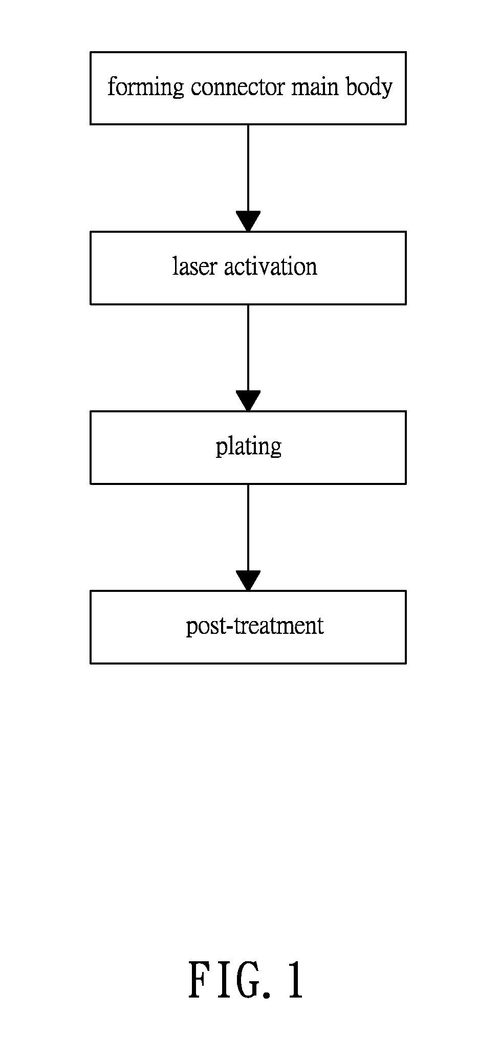
[0030]Please refer to FIG. 1. According to a preferred embodiment of the present invention, the process of manufacturing a low-profile connector includes the following steps: (1) forming connector main body; (2) laser activation; (3) plating; and (4) post-treatment.

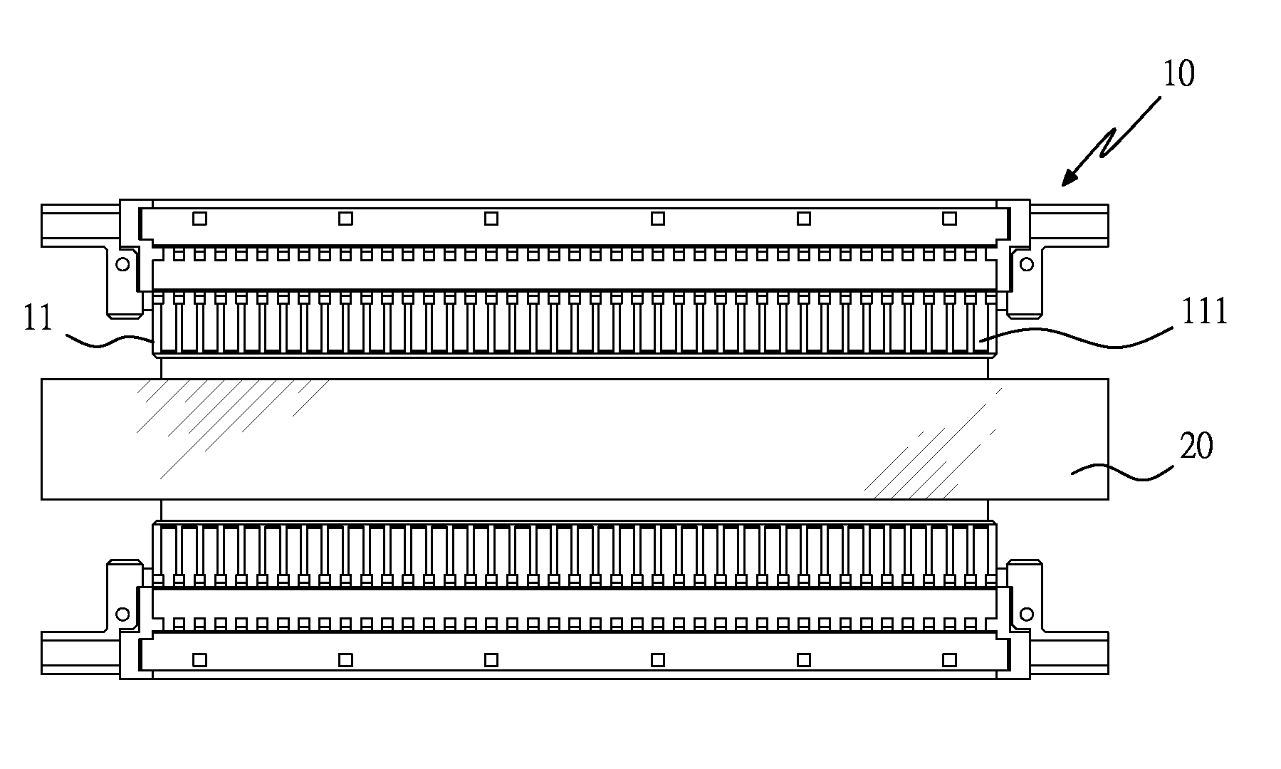
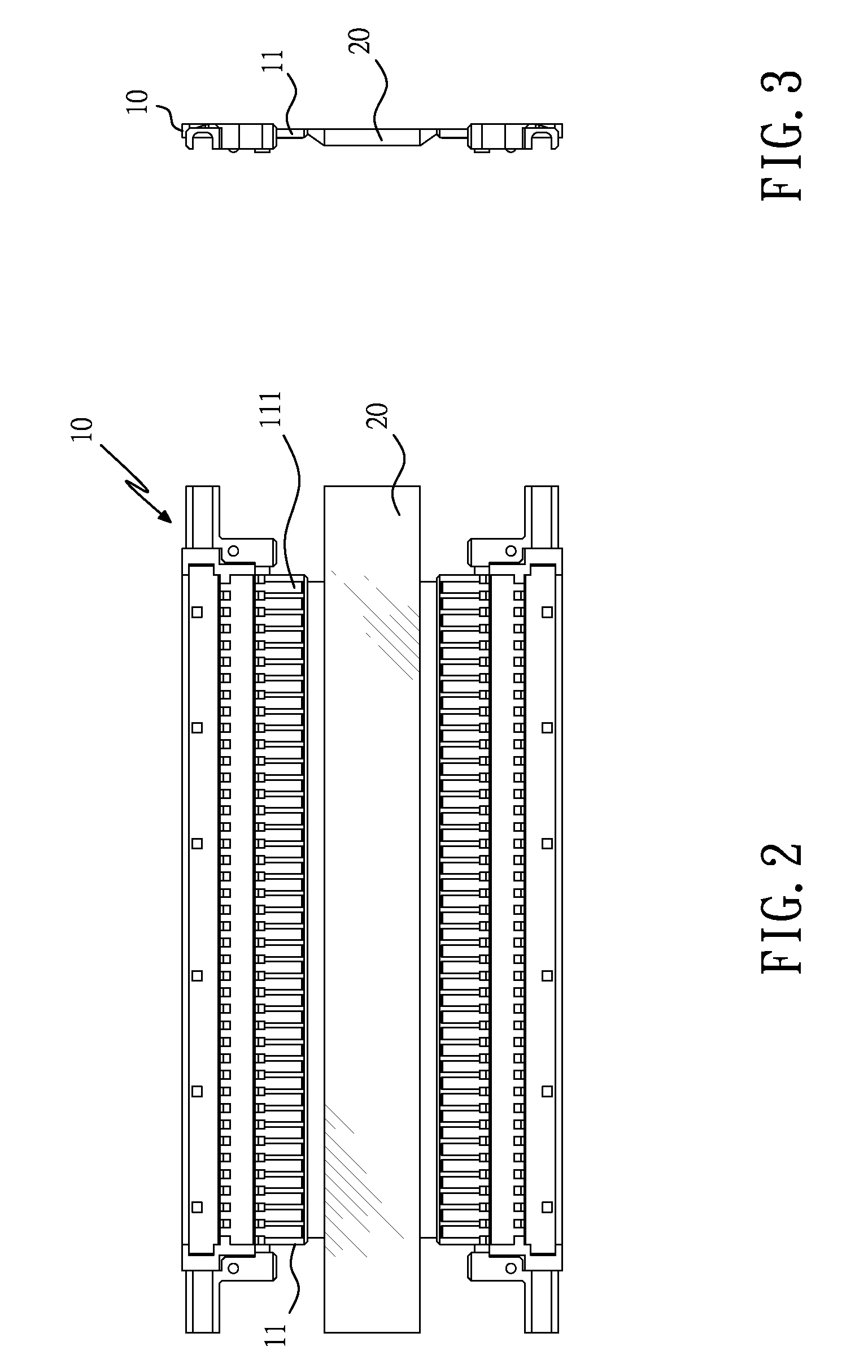
[0031]Please also refer to FIGS. 2 to 4. In the first step of forming connector main body, at least one connector m...


PUM

PropertyMeasurementUnit
areasaaaaaaaaaa
electrically conductingaaaaaaaaaa
thicknessaaaaaaaaaa

Abstract

A process of manufacturing low-profile connector includes the steps of (a) forming connector main body, (b) laser activation, (c) plating, and (d) post-treatment. The connector main body for low-profile connector so manufactured includes integrally formed pin terminals to effectively reduce the costs for researching and developing production engineering and making molds, to simplify processing procedures and save a lot of time and labors that are otherwise needed to process metal pins and separated half shells, and to effectively reduce the stock of components and save the warehousing management cost. Moreover, the present invention provides simplified and automated manufacturing process to omit manual assembling and accordingly, save labor cost for subsequent assembling and enable mass production.

Description

BACKGROUND OF THE INVENTION[0001]1. Field of the Invention[0002]The present invention relates to a process of manufacturing low-profile connector, and more particularly to a process of manufacturing connector main bodies for low-profile connectors for data transmission among electronic products.[0003]2. Description of the Prior Arts[0004]It is a common technique in the electronic industry to use a connector to bridge or connect two separate electronic devices at their connecting ends for signal and data transmission. There are tremendous types and models of connectors. However, most general connectors, when viewing from their structure, include a shell and a plurality of parallelly arranged metal pins enclosed in the shell. By fixedly welding the metal pins of the connector to an end of a cable, signal and data can be transmitted between two electronic devices via the connector. Conventionally, the shell of the connector is assembled from an upper and a lower half shell. Separate mo...

Claims


Application Information

Patent Timeline
Patent Type & Authority Applications(United States)
IPC IPC(8): C25D5/02
CPCC23C18/204C23C18/1657
Inventor CHOU, CHIN-YEH
Owner CHOU CHIH YEH
Why Eureka
Try Eureka