Light emitting diode with a step section between the base and the lens of the diode

a technology of light-emitting diodes and diodes, which is applied in the direction of basic electric elements, electrical apparatus, semiconductor devices, etc., can solve the problems of narrow viewing angle, reduced contrast, and difficulty in checking that a desired amount of resin material has been injected, so as to reduce contrast, narrow viewing angle, and increase contrast

Active Publication Date: 2008-09-11
BENCH WALK LIGHTING LLC
View PDF4 Cites 4 Cited by
  • Summary
  • Abstract
  • Description
  • Claims
  • Application Information

AI Technical Summary

Benefits of technology

[0012]According to the present invention, the step section which is provided around the out side of the lens having a hemispherical light emitting surface and which projects from the base prevents the resin material from being in direct contact with the lens. The height of the step section defines the amount of the resin material enough for reliably covering the lead section and the base of the LEDs. The cutout provided in the step section allows the operator to easily check that the amount of the resin material being injected is approaching a predetermined level. In this way, an appropriate amount of resin material can easily be injected, so that there is provided an LED that solves problems, such as reduced contrast and a narrower viewing angle. Furthermore, a plurality of the LEDs described above can be used to provide an LED display device with increased contrast and a wider viewing angle usable as an outdoor display.

Problems solved by technology

In general, when resin material is injected into the gaps among a plurality of arranged LEDs, it is difficult to check that a desired amount of resin material (or the amount that provides an appropriate height) has been injected.
In this case, light emitted from the lens will be absorbed by the resin material, resulting in reduced contrast and a narrower viewing angle.

Method used


Image

  • Light emitting diode with a step section between the base and the lens of the diode
  • Light emitting diode with a step section between the base and the lens of the diode
  • Light emitting diode with a step section between the base and the lens of the diode

Examples


Embodiment Construction

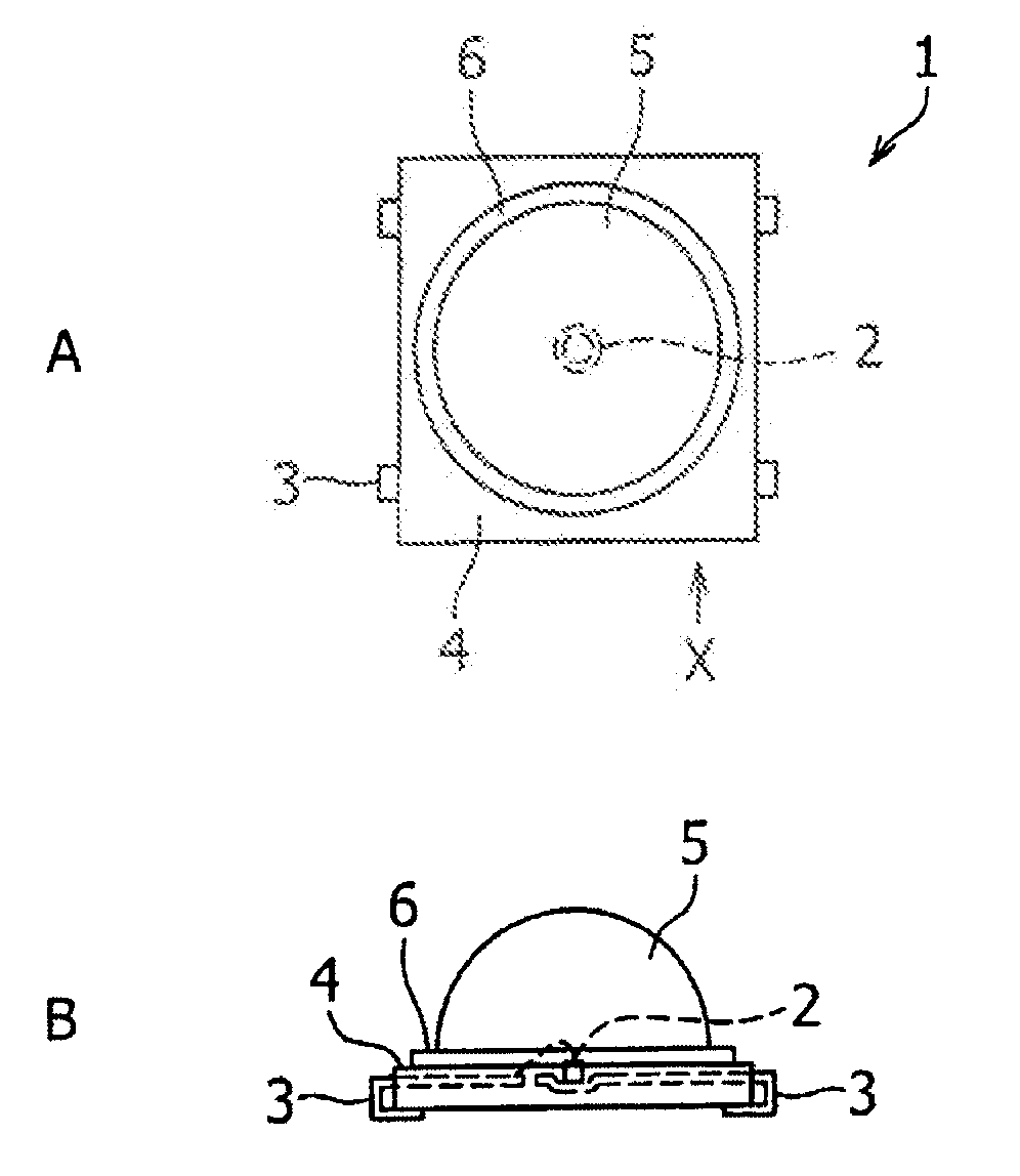
[0013]FIGS. 1A and 1B show a light emitting diode 1 used to implement the present invention. FIG. 1A shows the LED used to implement the present invention when viewed toward the light emitting surface side of the lens in the direction perpendicular to the base. FIG. 1B shows the LED shown in FIG. 1A when viewed in the direction X (direction parallel to the base).

[0014]The light emitting diode 1 includes a light emitting element 2, such as an LED element, a lead section or lead frame 3 that supplies power to the light emitting element 2, a base 4 that covers the lead section 3, a lens 5 having a hemispherical light emitting surface and connected to the base 4 to cover the light emitting element 2, and a step section 6 disposed such that it surrounds the outer side of the lens 5, part of the step section 6 having a different width. The step section 6 has a height that defines the amount of resin material enough for covering the lead section or lead frame 3 and the base 4.
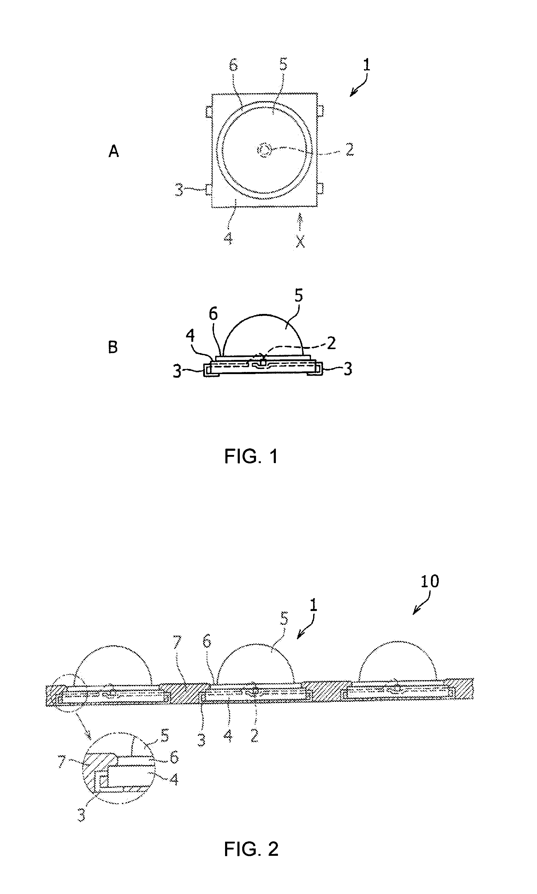
[0015]FIG. 2 ...


PUM


Abstract

[Problem to be Solved]It is to be made easy to arrange light emitting diodes, each including a lens having a hemispherical light emitting surface, and cover the base of the light emitting diodes with resin material.
[Solution]
A light emitting diode 1 has a light emitting element 2, a lead section 3 that supplies power to the light emitting element 2, a base 4 that covers the lead section 3, a lens 5 having a convex light emitting surface and connected to the base 4 to cover the light emitting element 2, and a step section 6 disposed such that it surrounds the outer side of the lens 5, part of the step 6 having a different width. The step section 6 has a height that defines the amount of resin material enough to cover the lead section 3. There is also provided a light emitting diode display device 10 using a plurality of such light emitting diodes.

Description

TECHNICAL FIELD[0001]The present invention relates to a light emitting diode (hereinafter referred to as “LED”) to be used in a display, such as an outdoor display.BACKGROUND ART[0002]A plurality of LEDs, each including a lens having a convex light emitting surface (or a bullet-shaped lens) and fixed to a base, are used as an outdoor display. FIGS. 5A and 5B show such a conventional LED. FIG. 5A is a top view of a conventional LED 100 having a convex lens, and FIG. 5B is a front view of the LED shown in FIG. 5A viewed from the direction Y. As shown in FIGS. 5A and 5B, the conventional LED 100 includes an LED element 20, a lead section or a lead frame 30 connected to the LED element 20, and a base 40 that supports a convex lens 50 that covers the LED element 20.[0003]When a plurality of the LEDs 100 described above are used to form an LED display device 200, black resin material is generally provided in the gaps among the LEDs 100 in order to prevent reduction in contrast due to refl...

Claims


Application Information

Patent Timeline
Patent Type & Authority Applications(United States)
IPC IPC(8): H01L29/22
CPCH01L33/486H01L33/58H01L2924/0002H01L2924/00
Inventor TAKEKUMA, AKIRA
Owner BENCH WALK LIGHTING LLC
Why Eureka
Try Eureka