
Apparatus and Method for Monitoring and/or Load Applied to a Mammal

a technology of muscle activity and apparatus, applied in the field of apparatus and a method for monitoring strain and/or load applied to the body of a vertebral mammal, can solve the problems of compensable workplace injuries, preventing back injuries, and causing major workplace safety challenges, and achieve the effect of solving ambiguous readings of muscle activity

Active Publication Date: 2008-09-11
RONCHI ANDREW J +1
View PDF6 Cites 15 Cited by
  • Summary
  • Abstract
  • Description
  • Claims
  • Application Information

AI Technical Summary

Benefits of technology

[0019]Angular displacement of the accelerometer may be calculated by multiplying the raw signal value by the gain constant (p) and adding the offset constant (o). The resulting value may represent the G force acting on one axis. For a resultant G force in three dimensions, three axes trigonometry may be used, wherein x is the horizontal axis, y is the vertical axis and z is the ‘through page’ axis. Using 3D Pythagoras and an inverse tangent formula, two angles may be derived to give a position for the accelerometer. One accelerometer in isolation may only give a direction of movement, but when there are two accelerometers, the difference between angles of the two accelerometers may represent a change in position (in degrees) of one accelerometer compared to the other accelerometer. This may allow the apparatus to calculate angular position of the lumbar spine, at any moment in time, within a three dimensional axis.

Problems solved by technology

Preventing back injuries presents a major workplace safety challenge.
Moreover, one-quarter of compensation indemnity claims involve back injuries, costing industry billions of dollars on top of the pain and suffering borne by employees.
A documented cause of compensable workplace injuries is due to manual handling tasks such as lifting, placing, carrying, holding and lowering of materials.
One difficulty in preventing and / or treating lower back injury is due to a lack of facility to objectively measure movements and stresses placed on the lower back over time and therefore the risks that are associated with use of the lower back when undertaking a task or activity that presents a risk of injury.

Method used


Image

  • Apparatus and Method for Monitoring and/or Load Applied to a Mammal
  • Apparatus and Method for Monitoring and/or Load Applied to a Mammal
  • Apparatus and Method for Monitoring and/or Load Applied to a Mammal

Examples


Embodiment Construction

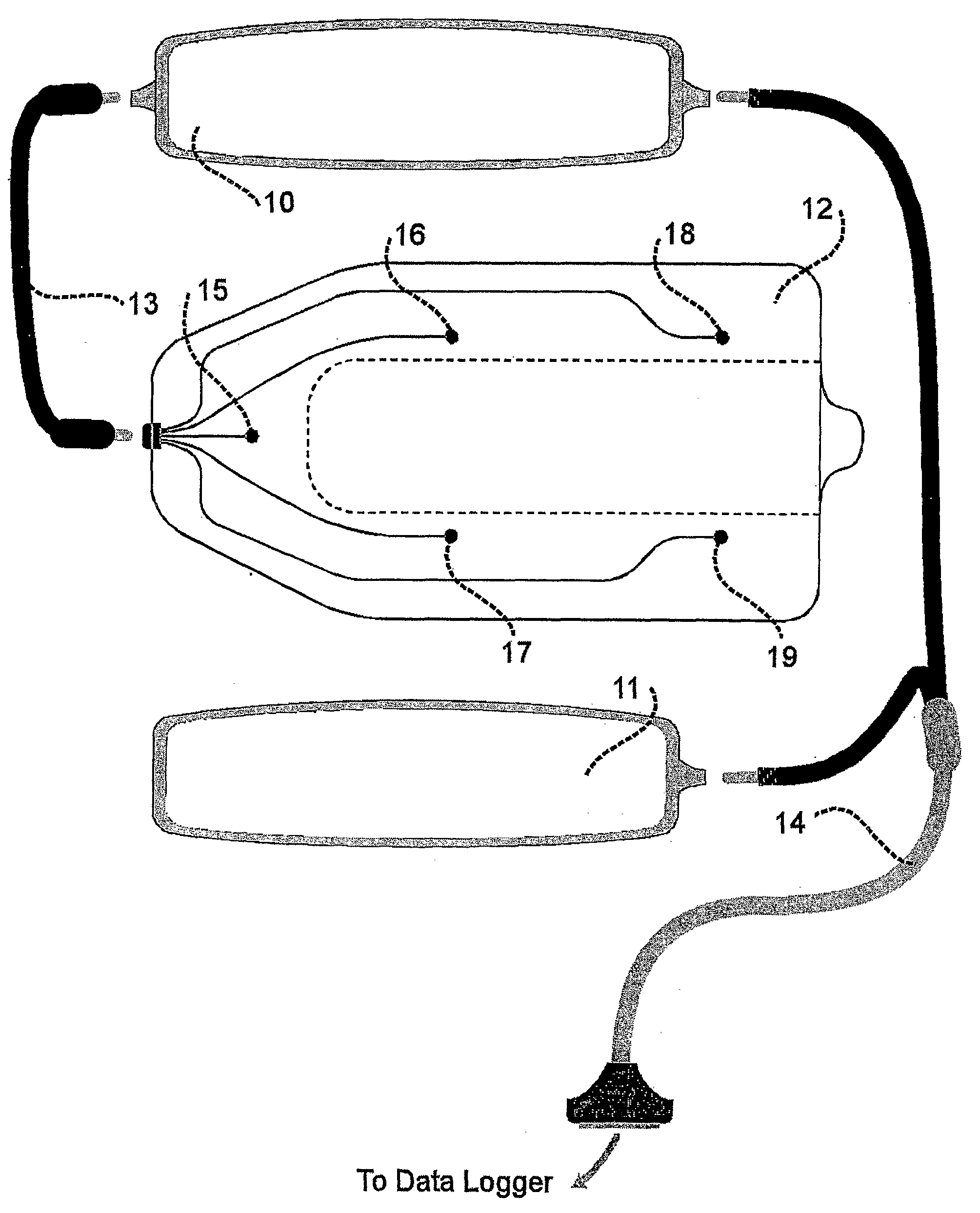
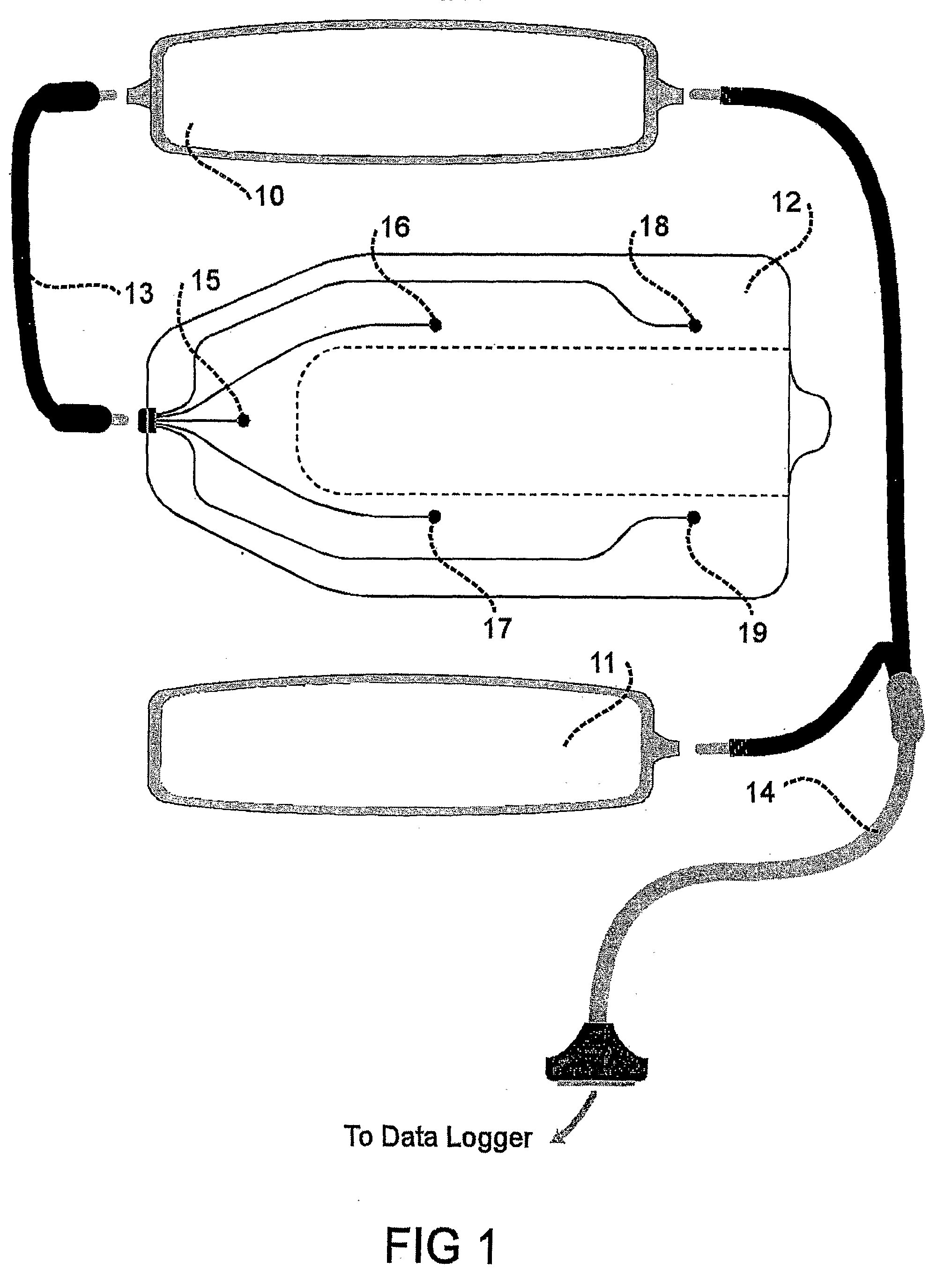
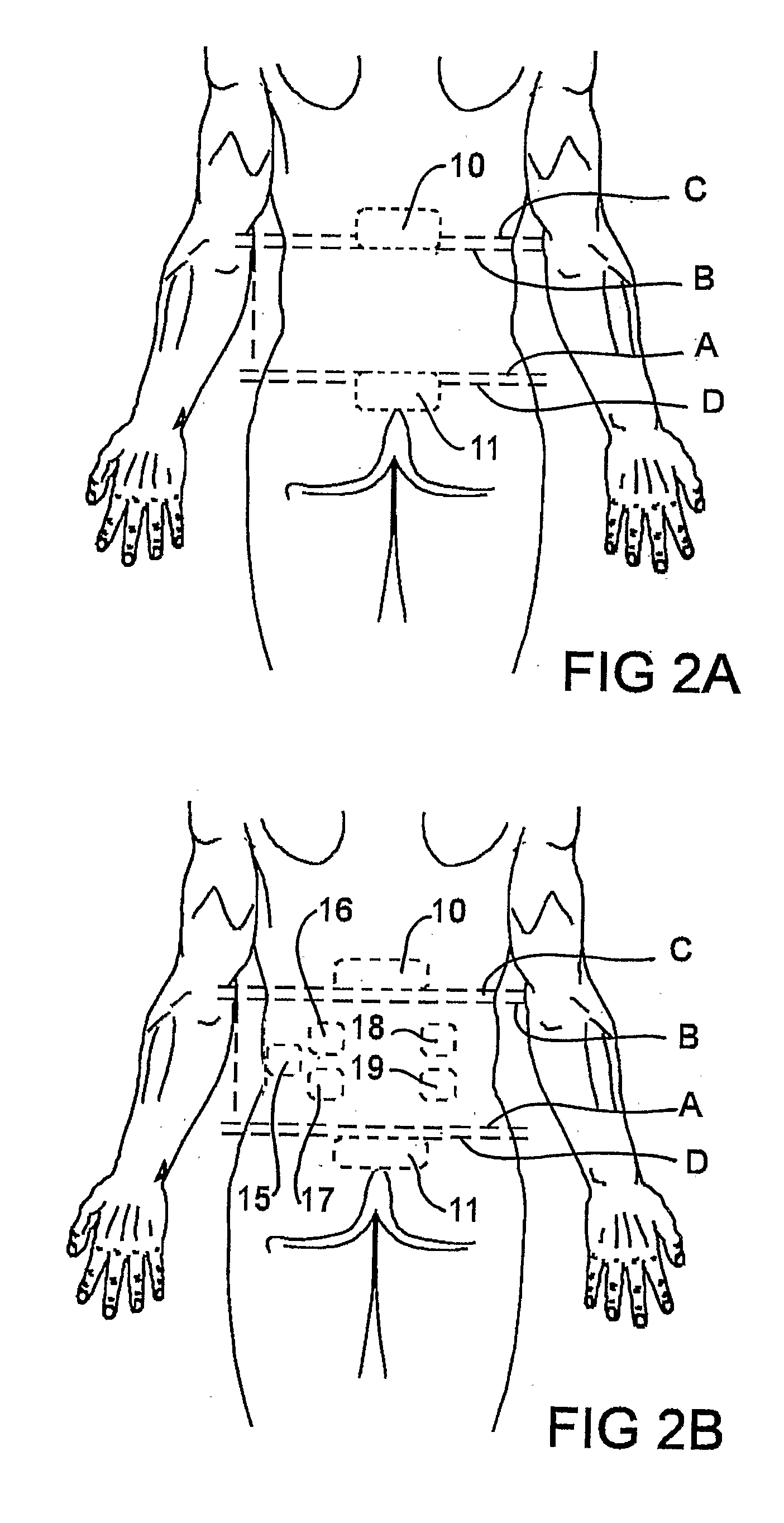
[0053]FIG. 1 shows a pair of transducer pads 10, 11 and an EMG electrode assembly 12. Pads 10, 11 and EMG assembly are connected to a data logger (not shown) via detachable plug in cables 13, 14. Transducer pads are positioned on the back of a person being monitored as described with reference to FIGS. 2A and 2B.

[0054]The transducer pads 10, 11 are attached to the skin in any suitable manner such as via adhesive tape. Each transducer pad 10, 11 incorporates one or more accelerometers. Preferably angular changes of lumbar spine orientation are measured by use of four accelerometers, two of which are placed at the upper lumbar spine and other two, at the lower lumbar spine.

[0055]If one accelerometer is used in each transducer pad it should be mounted such that it is located centrally over the spine. Each transducer pad 10, 11 may be at least 10 cm wide and may include a gyroscope to provide rotational data.

[0056]EMG electrode assembly 12 includes a plurality of EMG electrodes 15-19. E...


PUM


Abstract

Apparatus is disclosed for monitoring strain and / or load applied to the body of a vertebral mammal. The apparatus includes means (10, 11) for measuring position of the body relative to an inertial frame of reference and for providing first data indicative of the position, wherein the means for measuring position includes at least one inertial sensor such as an accelerometer. The apparatus includes means (12, 15-19) for measuring muscle activity and for providing second data indicative of the muscle activity. The apparatus also includes means for storing the data and means for processing the data to provide a measure of strain and / or load to the body. The strain and / or load is typically applied to the back of the mammal. A method of monitoring strain and / or load applied to the body of the vertebral mammal is also disclosed.

Description

BACKGROUND OF THE INVENTION[0001]The present invention relates to apparatus and a method for monitoring strain and / or load applied to the body of a vertebral mammal. The present invention is particularly suitable for monitoring strain and / or load applied to the back of the mammal including the lumbar spine and it will be described herein in this context. Nevertheless, it is to be understood that the present invention is not thereby limited to such applications. In this document use of the words strain and / or load in relation to the body of a mammal includes a reference to movements, muscle forces and loads including gravitational loads acting on the body of the mammal.[0002]Preventing back injuries presents a major workplace safety challenge. According to the Bureau of Labour Statistics in the United States, more than one million workers suffer back injuries each year. Back injuries account for one in every five workplace injuries or illnesses. Moreover, one-quarter of compensation ...

Claims


Application Information

Patent Timeline
Patent Type & Authority Applications(United States)
IPC IPC(8): A61B5/0488A61B5/22A61B5/00A61B5/04A61B5/103A61B5/11
CPCA61B5/0488A61B2562/0219A61B5/224A61B5/1126A61B5/389
Inventor RONCHI, ANDREW J.RONCHI, DANIEL M.
Owner RONCHI ANDREW J
Learn More