Specimen retrieval device

a specimen retrieval and device technology, applied in the field of surgical instruments, can solve the problems of uniform deficiency in providing a simple, efficient, practical specimen retrieval devi

Inactive Publication Date: 2008-09-11
THE HOLLIS GROUP
View PDF9 Cites 87 Cited by
  • Summary
  • Abstract
  • Description
  • Claims
  • Application Information

AI Technical Summary

Benefits of technology

[0008]Briefly stated, the present invention provides a surgical specimen retrieval device that allows one-handed use by incorporating a geared spool to amplify take up of a flexible line to close the mouth of the specimen bag after the surgical specimen is deposited in the bag. The retrieval device includes a spool with an attached gear that is rotated by movement of a deployment rod with serrated teeth. A flexible line has a proximal end attached to the spool and the distal end attached to the mouth of the bag. When the deployment reel is moved from an extended position to an inserted position, the spool rotates and pays out flexible line to allow the mouth of the deployed bag to open. Once a specimen is taken and deposited in the bag, the deployment rod is moved from the inserted position toward the extended position. This rod movement rotates the spool to take up the line and close the mouth of the bag. When the rod is moved to a fully retracted position, the teeth on the rod disengage from the gear, which allows the spool to rotate freely. The device is then removed from the trocar and the line is used to pull the bagged specimen from the body cavity.

Problems solved by technology

While all of the aforementioned prior art constructions are more than adequate for the basic purpose and function for which they have been specifically designed, they are uniformly deficient with respect to their failure to provide a simple, efficient, and practical specimen retrieval device that may be operated with one hand.

Method used


Image

  • Specimen retrieval device
  • Specimen retrieval device
  • Specimen retrieval device

Examples


Embodiment Construction

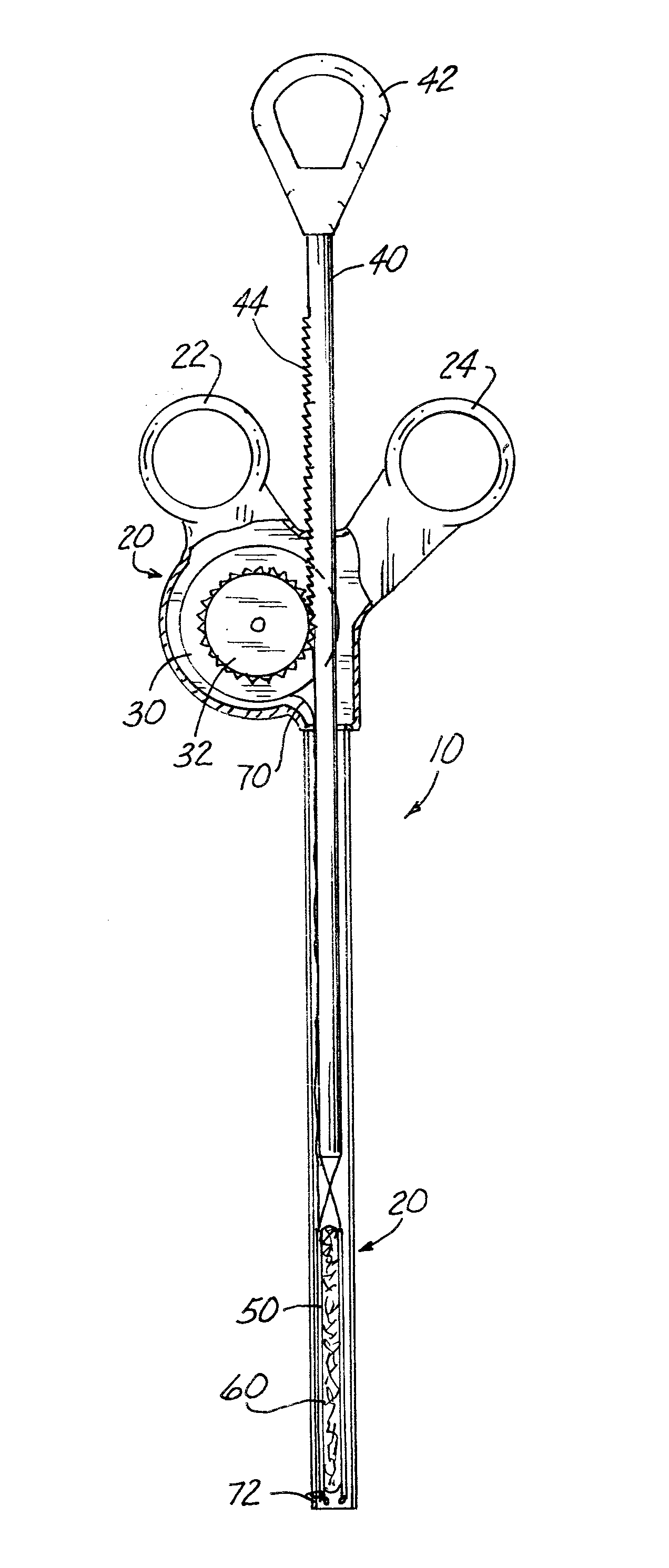
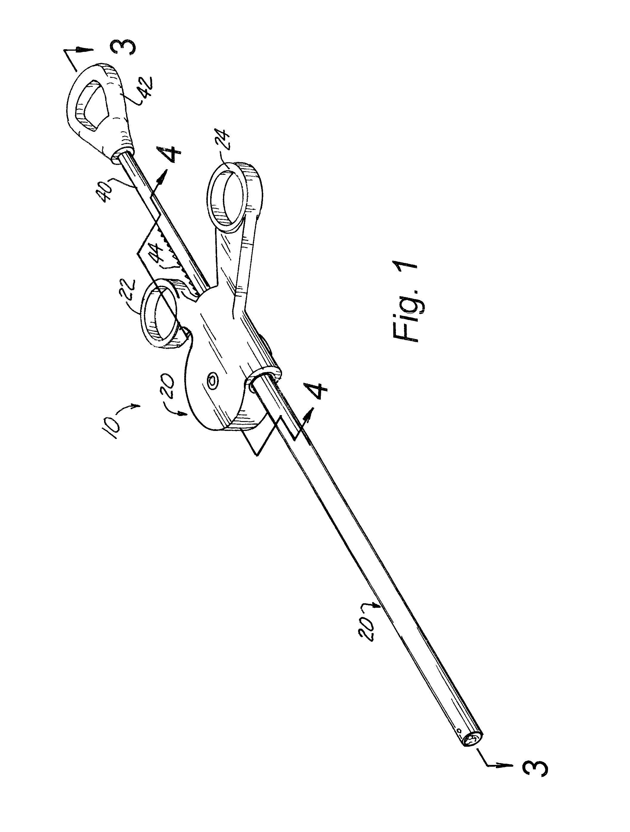
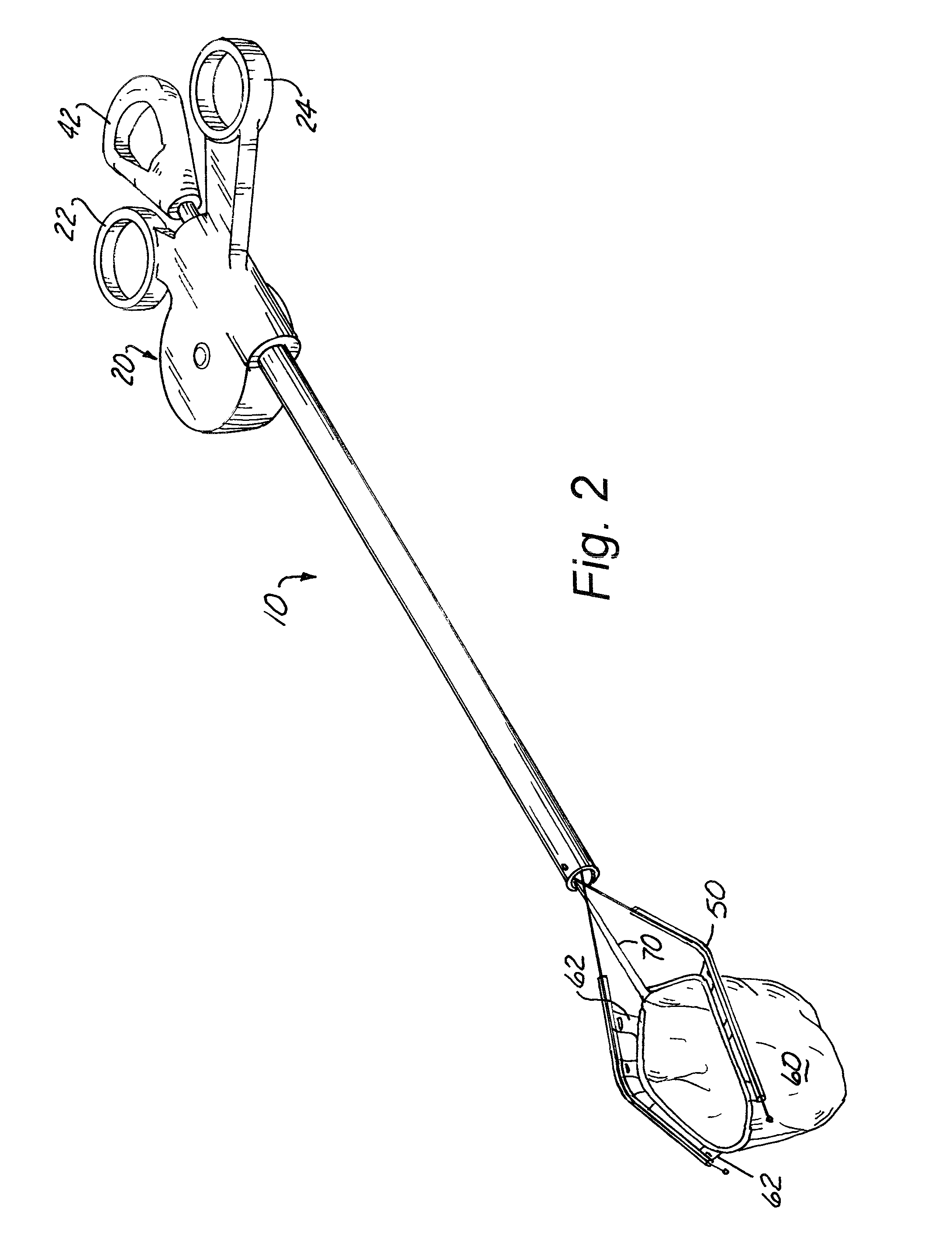
[0019]As can be seen by reference to the drawings, and in particular to FIG. 1, the specimen retrieval device that forms the basis of the present invention is designated generally by the reference number 10.

[0020]The components of this invention include the main housing 20 which contains a spool 30, a gear wheel 32 that interacts with a serrated deployment rod 40, a serrated deployment rod 40 with a self expanding rigid loop 50 attached to the distal end, a specimen retrieval bag 60 attached to the self expanding rigid loop 50, and a string 70 attached to the spool 30 and the bag 60. The main housing 20 is made of rigid plastic and is shaped like a long tube that is larger on the proximal end to accommodate the spool 30 and attached gear mechanism 32, and the deployment rod 40. The housing 20 includes finger holes 22, 24 for grasping the instrument 10 with the second and third fingers. The deployment shaft 40 is a long rigid plastic rod with a finger hole 42 for the thumb. It enters...


PUM


Abstract

The present invention provides a surgical specimen retrieval device that allows one-handed use by incorporating a geared spool to amplify take up of a flexible line to close the mouth of the specimen bag after the surgical specimen is deposited in the bag. The retrieval device includes a spool with an attached gear that is rotated by movement of a deployment rod with serrated teeth. A flexible line has a proximal end attached to the spool and the distal end attached to the mouth of the bag. When the deployment reel is moved from an extended position to an inserted position, the spool rotates and pays out flexible line to allow the mouth of the deployed bag to open. Once a specimen is taken and deposited in the bag, the deployment rod is moved from the inserted position toward the extended position. This rod movement rotates the spool to take up the line and close the mouth of the bag. When the rod is moved to a fully retracted position, the teeth on the rod disengage from the gear, which allows the spool to rotate freely. The device is then removed from the trocar and the line is used to pull the bagged specimen from the body cavity.

Description

CROSS REFERENCE TO RELATED APPLICATIONS[0001]This application claims the benefit of U.S. Provisional Patent Application Ser. No. 60 / 893,332 filed Mar. 6, 2007 entitled “ONE HANDED MINIMALLY INVASIVE SPECIMEN RETRIEVAL DEVICE WITH SPOOL / GEAR MECHANISM”, which is incorporated herein by reference.BACKGROUND OF THE INVENTION[0002]1. Field of the Invention[0003]The present invention relates to the field of surgical instruments, and more particularly to a specimen retrieval device for use in minimally invasive surgery to retrieve a specimen from a body cavity.[0004]2. Description of Related Art[0005]As can be seen by reference to the following U.S. Pat. No. 5,354,303; U.S. Pat. No. 5,647,372; U.S. Pat. No. 5,971,995; U.S. Pat. No. 6,383,197; WO04064669; and U.S. Publn. 20040138587, the prior art is replete with myriad and diverse specimen retrieval devices.[0006]While all of the aforementioned prior art constructions are more than adequate for the basic purpose and function for which they...

Claims


Application Information

Patent Timeline
Patent Type & Authority Applications(United States)
IPC IPC(8): A61B17/00
CPCA61B17/00234A61B2017/2923A61B2017/00287
Inventor HOLLIS, JEFFREY D.HOLLIS, GREGORY D.WILSON, JOHN TROY
Owner THE HOLLIS GROUP
Why Eureka
Try Eureka