Cover Capable of Supporting Diary or Calendar

a diary or calendar technology, applied in the field of multi-purpose supportable covers, can solve the problems of not being able to check appointments or schedules written on calendars, not being able to carry calendars, and not being able to check appointments or schedules easily, so as to improve portability and usability

Inactive Publication Date: 2008-09-18
PARK JEONG WOO
View PDF3 Cites 0 Cited by
  • Summary
  • Abstract
  • Description
  • Claims
  • Application Information

AI Technical Summary

Benefits of technology

[0006]The present invention provides a multipurpose supportable cover improved in portability and usability so as to serve as both a scheduler and a calendar.

Problems solved by technology

However, schedulers or calendars are sold as separate products and used separately, so that they are not convenient for users.
For example, in home or offices, users usually write down important schedules, anniversaries, appointments, etc. in calendars, but calendars are not easy to be carried.
Hence, it is not easy to check appointments or schedules written down on calendars while going out or moving.
On the other hand, current schedulers cannot be used standing on a table although including a calendar.

Method used


Image

  • Cover Capable of Supporting Diary or Calendar
  • Cover Capable of Supporting Diary or Calendar
  • Cover Capable of Supporting Diary or Calendar

Examples


first embodiment

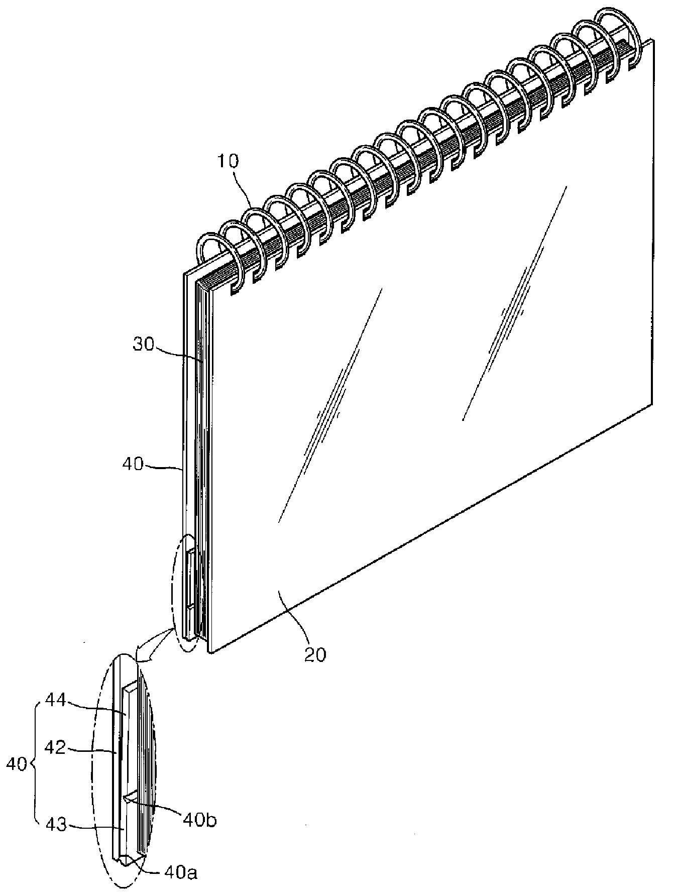
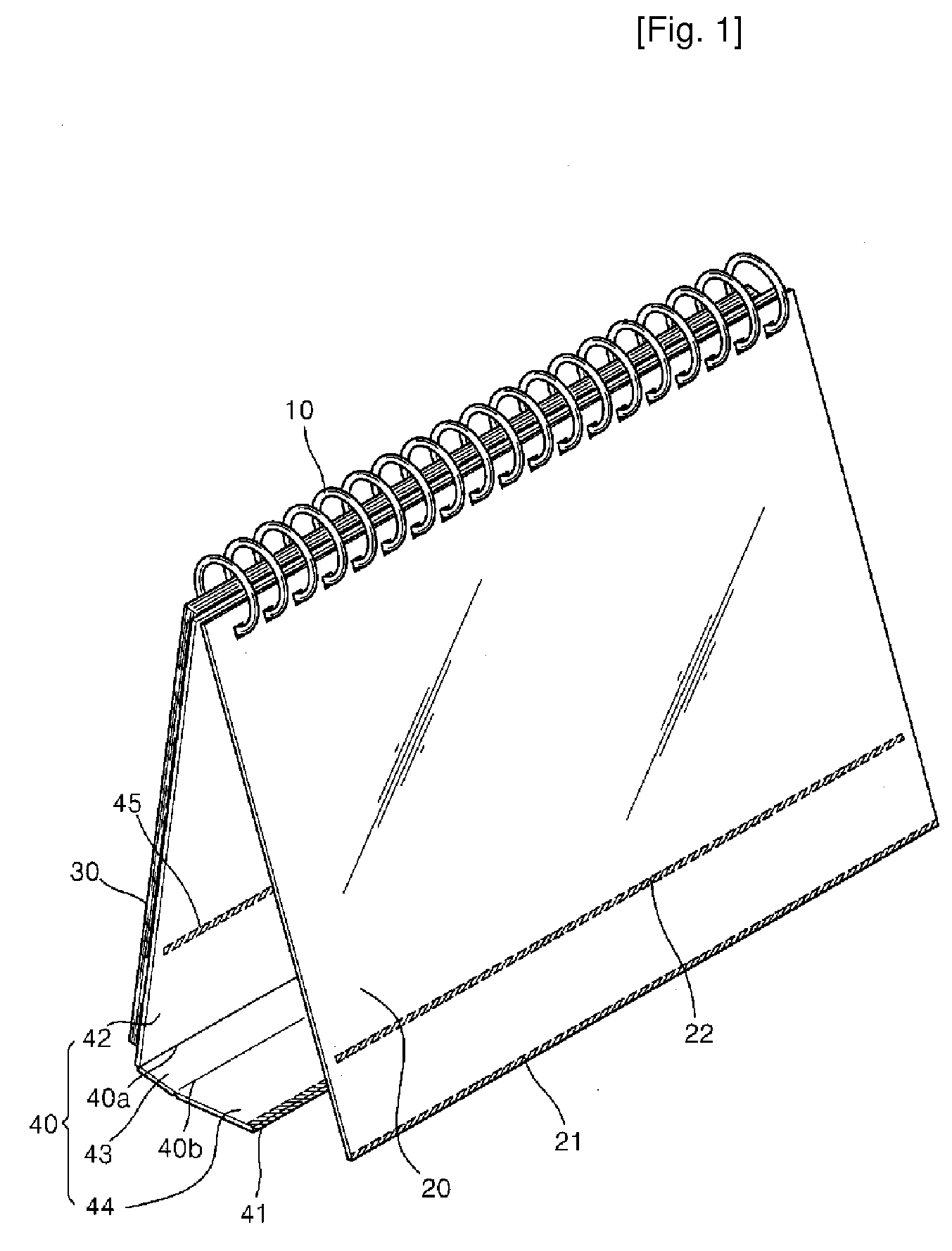
[0041]FIG. 1 is a perspective view of a multipurpose supportable cover according to the present invention. FIG. 2 is a perspective view illustrating the supportable cover shown in FIG. 1 that is in a standing state. FIG. 3 is a perspective view illustrating the multipurpose supportable cover shown in FIG. 1 when a second sub-rear cover is folded to face a front cover in order to carry the supportable cover.

[0042]FIG. 4 is a perspective view illustrating the multipurpose supportable cover shown in FIG. 1 when a first sub-rear cover and the second sub-rear cover are folded to face a main rear cover in order to frequently use the supportable cover. FIG. 5 is a perspective view illustrating the use of a second sub-rear cover narrower than the main rear cover instead of the second sub-rear cover included in the multipurpose supportable cover shown in FIG. 1.

[0043]As illustrated in FIGS. 1 through 5, the supportable cover according to the first embodiment includes a front cover 20, a fill...

second embodiment

[0064]A multipurpose supportable cover according to the present invention will now be described with reference to FIGS. 7 and 8.

[0065]FIG. 7 is a perspective view of a multipurpose supportable cover according to a second embodiment of the present invention. FIG. 8 is a perspective view illustrating the use of a second sub-rear cover 144′ narrower than a main rear cover 142 instead of a second sub-rear cover 144 included in the multipurpose supportable cover shown in FIG. 7.

[0066]As illustrated in FIGS. 7 and 8, the multipurpose supportable cover according to the second embodiment includes a binder 110, a front cover 120, a filler page portion 130, and a rear cover 140 that are similar to those of the first embodiment.

[0067]A first magnet piece 121 is installed on the lower end of the front cover 120. A second magnet piece 122 is installed over the first magnet piece 121. Although the first and second magnet pieces 121 and 122 are illustrated as long bars formed of a magnetic materia...

third embodiment

[0075]A multipurpose supportable cover according to the present invention will now be described with reference to FIGS. 9, 10, and 11.

[0076]FIG. 9 is a perspective view of a multipurpose supportable cover according to a third embodiment of the present invention. FIG. 10 is a perspective view illustrating the multipurpose supportable cover shown in FIG. 9 that is in a standing state. FIG. 11 is a perspective view illustrating the multipurpose supportable cover shown in FIG. 9 when a sub-rear cover 243 is folded to face a stepped portion 242a in order to carry the supportable cover.

[0077]As illustrated in FIGS. 9 through 11, the supportable cover according to the third embodiment includes a binder 210, a front cover 220, a filler page portion 230, and a rear cover 240 that are similar to those of the first and second embodiments.

[0078]The rear cover 240 includes a main rear cover 242 and the sub-rear cover 243 that are partitioned by a folding line 240a. An insertion piece 244 having ...


PUM


Abstract

A multipurpose supportable cover having improved portability and usability, the cover including a front cover 20, a filler page portion 30, and a rear cover 40 that are bound by a binder 10, wherein a first iron piece 21 is installed on a lower end of the front cover 20, the rear cover 40 includes a main rear cover 42, a first sub-rear cover 43, and a second sub-rear cover 44 that are partitioned by first and second folding lines 40a and 40b, and a magnet piece 41 to be attached to the first iron piece 21 is installed on a lower end of the second sub-rear cover 44.

Description

TECHNICAL FIELD[0001]The present invention relates to a multipurpose supportable cover that provides improved portability and usability.BACKGROUND ART[0002]Schedulers include a filler page portion on which various forms of scratch paper to write schedules, memos, addresses, telephone numbers, etc. thereon, a map including various useful pieces of information, and a route map including information such as subway routes are printed. Such schedulers are widely used by salary persons and students.[0003]Meanwhile, calendars are manufactured by binding pages displaying months or weeks with two thick boards serving as a front cover and a rear cover. When the front and rear cover are stretched out, the calendar turns into a triangular support and is thus used standing on a table.[0004]Such schedulers or calendars are very useful in daily lives or business and thus widely used.[0005]However, schedulers or calendars are sold as separate products and used separately, so that they are not conve...

Claims


Application Information

Patent Timeline
Patent Type & Authority Applications(United States)
IPC IPC(8): B42D3/10
CPCB42D3/10Y10T24/11B42P2241/12B42D5/043B42D1/08B42D3/02B42D5/045B42P2241/02
Inventor PARK, JEONG-WOO
Owner PARK JEONG WOO
Why Eureka
Try Eureka