Control unit for suspension using single pressure sensor

a control unit and pressure sensor technology, applied in the direction of fluid pressure control, process and machine control, instruments, etc., can solve the problems of affecting the overall system integrity, unable to provide desired ride and performance characteristics, and rendering the vehicle inoperabl

Inactive Publication Date: 2008-09-18
ARVINMERITOR TECH
View PDF19 Cites 18 Cited by
  • Summary
  • Abstract
  • Description
  • Claims
  • Application Information

AI Technical Summary

Benefits of technology

[0006]A method and apparatus for adjusting a suspension includes providing a plurality of pneumatic suspension elements, a plurality of pneumatic control valves, and a manifold. Each pneumatic suspension element is associated with one pneumatic control valve. The manifold includes a supply valve to be fluidly connected to an air supply, an exhaust valve, and a single pressure sensor. The manifold is fluidly connected to each of the plurality of pneumatic control valves such that the supply valve can supply air to, and the exhaust valve can exhaust air from, the pneumatic suspension elements via an associated one of the pneumatic control valves.

Problems solved by technology

For example, mechanical suspensions for military applications are robust and can operate reliably under harsh environmental conditions, but often do not provide desired ride and performance characteristics.
A single failure, such as a leak for example, in an air supply configuration can affect overall system integrity rendering a vehicle inoperable.
Although these systems are simple and robust, they have limitations.

Method used


Image

  • Control unit for suspension using single pressure sensor
  • Control unit for suspension using single pressure sensor
  • Control unit for suspension using single pressure sensor

Examples


Embodiment Construction

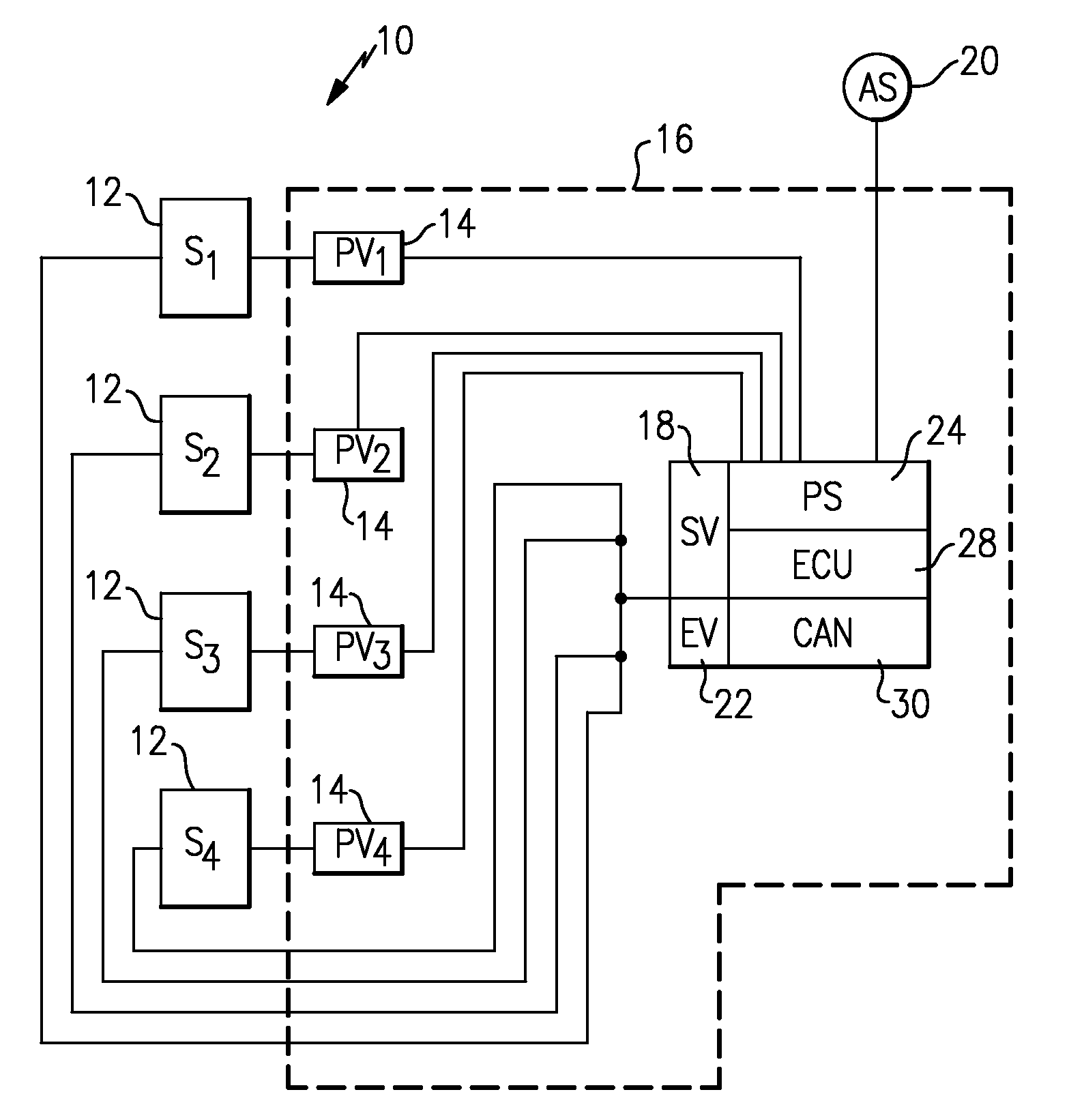
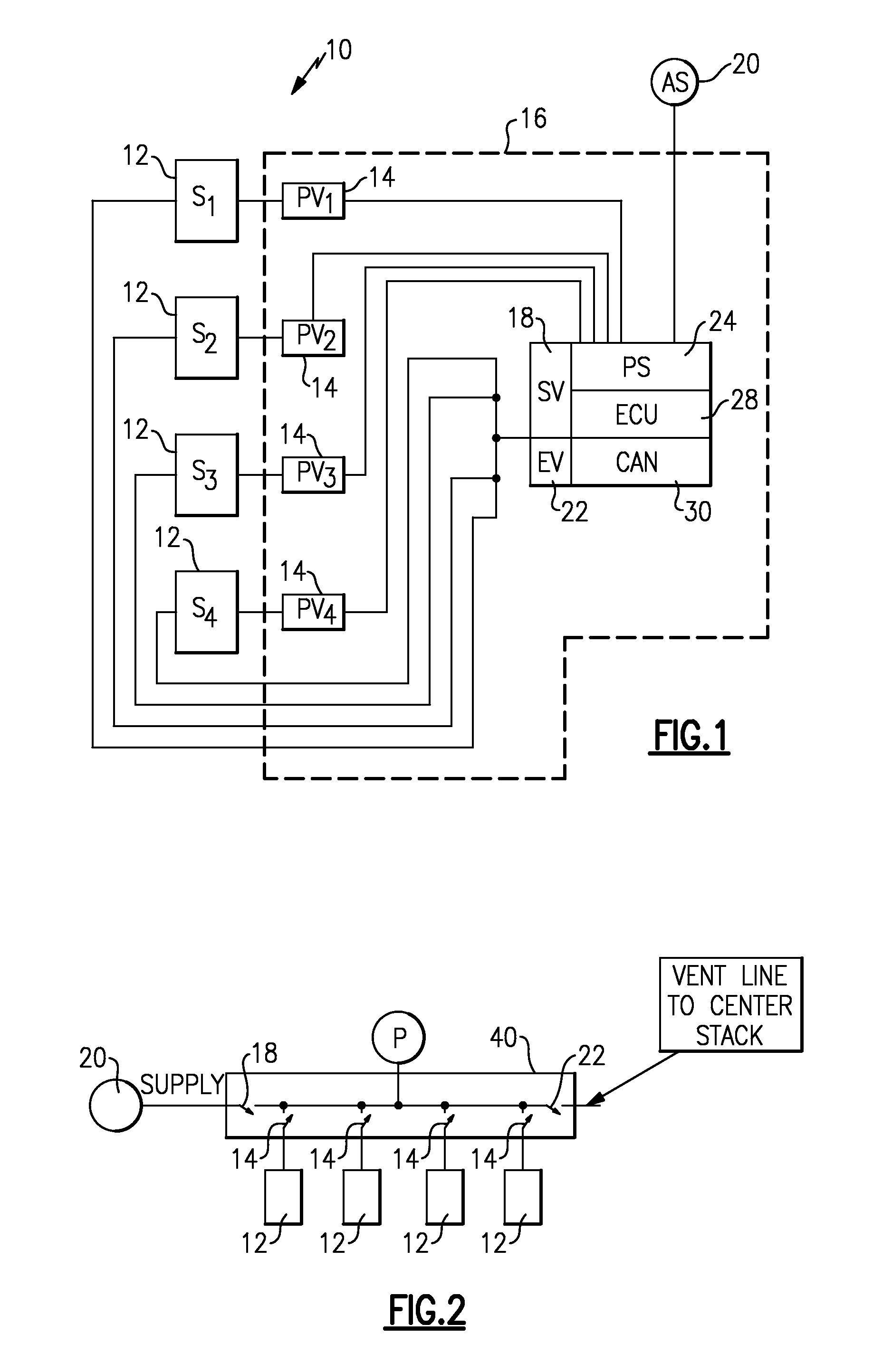
[0015]A suspension for a vehicle, such as a military vehicle for example, is shown generally at 10 in FIG. 1. The suspension 10 includes a plurality of pneumatic suspension elements 12, such as air springs for example. In the example configuration shown, four (4) air springs S1-4 are shown, however, fewer or additional air springs could be utilized in the suspension 10 as needed.

[0016]Each pneumatic suspension element 12 is associated with one pneumatic control valve 14. In the example shown, the pneumatic control valves 14 comprise solenoid valves, however, other types of valves could also be used. The pneumatic control valves 14 are normally in a closed position such that each pneumatic suspension element 12 is isolated from other pneumatic suspension elements 12. Thus, a failure or leak of one of the pneumatic suspension elements 12 does not affect the performance of the remaining pneumatic suspension elements 12.

[0017]A manifold 16 is in fluid communication with each of the pneu...


PUM


Abstract

A vehicle suspension includes a plurality of pneumatic suspension elements with each pneumatic suspension element being associated with one pneumatic control valve. A common manifold is fluidly connected to each of the pneumatic control valves. The manifold includes a supply valve that is connected to an air supply, an exhaust valve, and a single pressure sensor. The single pressure sensor is used to measure a pressure level at each of the pneumatic suspension elements. A controller cooperates with the manifold to individually adjust pressure levels of each of the pneumatic suspension elements based on the individually sensed pressure levels. The controller can use the sensed pressure levels to adjust suspension ride height, identify system leaks and isolate defective suspension elements, identify uneven pressure distribution, and to determine a load supported on the pneumatic suspension elements.

Description

TECHNICAL FIELD[0001]The subject invention generally relates to a method and apparatus for adjusting a pneumatic suspension, including providing a control unit with a single pressure sensor for a plurality of pneumatic suspension elements.BACKGROUND OF THE INVENTION[0002]Vehicles can be configured to utilize different types of suspensions including mechanical leaf spring suspensions, pneumatic suspensions, and active or semi-active suspensions, for example. Each type of suspension has certain advantages / disadvantages for associated vehicle applications. Certain types of suspensions are more suitable for certain vehicle applications than others. For example, mechanical suspensions for military applications are robust and can operate reliably under harsh environmental conditions, but often do not provide desired ride and performance characteristics. Pneumatic suspensions provide more desirable ride characteristics but are relatively new to military vehicle applications. Pneumatic susp...

Claims


Application Information

Patent Timeline
Patent Type & Authority Applications(United States)
IPC IPC(8): B60G17/052B60G11/27G05D16/20
CPCB60G17/0185B60G2800/914B60G2202/152B60G2206/0116B60G2400/51222B60G2401/11B60G2401/90B60G2500/2012B60G2500/203B60G2500/302B60G2600/042B60G2600/08B60G2600/18B60G2600/26B60G17/0523
Inventor SMITH, MARK C.CARON, VERN A.MALEKI, ALI F.
Owner ARVINMERITOR TECH
Why Eureka
Try Eureka