Landing gear strut extender

a technology of extension strut and landing gear, which is applied in the direction of landing gear, transportation and packaging, undercarriage, etc., can solve the problems of adding considerable weight and some expense to the aircraft, reducing the service life of the aircraft, and re-creating the existing configuration of landing gear in order to gain length, etc., to reduce the cost of engine fod damage, prolong the landing gear, and reduce the effect of costly fod damag

Active Publication Date: 2013-06-11
HYDRO AIRE AEROSPACE CORP
View PDF15 Cites 16 Cited by
  • Summary
  • Abstract
  • Description
  • Claims
  • Application Information

AI Technical Summary

Benefits of technology

[0007]Injecting fluid into the strut: Normally, when taxiing on the ground the landing gear strut is nearly fully compressed by the aircraft weight that it is supporting. An apparatus according to the present invention would inject fluid into the strut after landing as the full weight of this aircraft is supported by the struts. Adding fluid to the strut causes the strut to extend, but does not change the volume of gas in the strut and hence does not change the characteristics of the spring rate of the gas. Lengthening the strut provides more ground clearance for the engines, thus allowing a more efficient inlet design and less exposure to FOD damage. The shock absorbing and taxi “handling” of the strut are not affected because the added oil is essentially incompressible and the gas volume (which provides the shock absorbing “spring”) is not changed.
[0009]The invention offers the advantage of providing a longer landing gear for certain operations of the aircraft where that is desirable, without having to pay the cost and weight of a longer landing gear. This is particularly true with respect to the ability to design a more fuel-efficient engine inlet and reduce costly FOD damage to engines. In addition, the invention allows the amount of fluid in the gear to be optimized for various weight and temperature conditions which may allow further weight saving and performance advantages to the aircraft.

Problems solved by technology

However, a longer landing gear adds considerable weight and some expense to the aircraft.
This is particularly true when modifying an existing aircraft design to stretch the fuselage or add larger diameter engines, etc., because revising an existing landing gear configuration in order to gain length would be extremely expensive as well as add considerable weight.

Method used


Image

  • Landing gear strut extender
  • Landing gear strut extender

Examples


Embodiment Construction

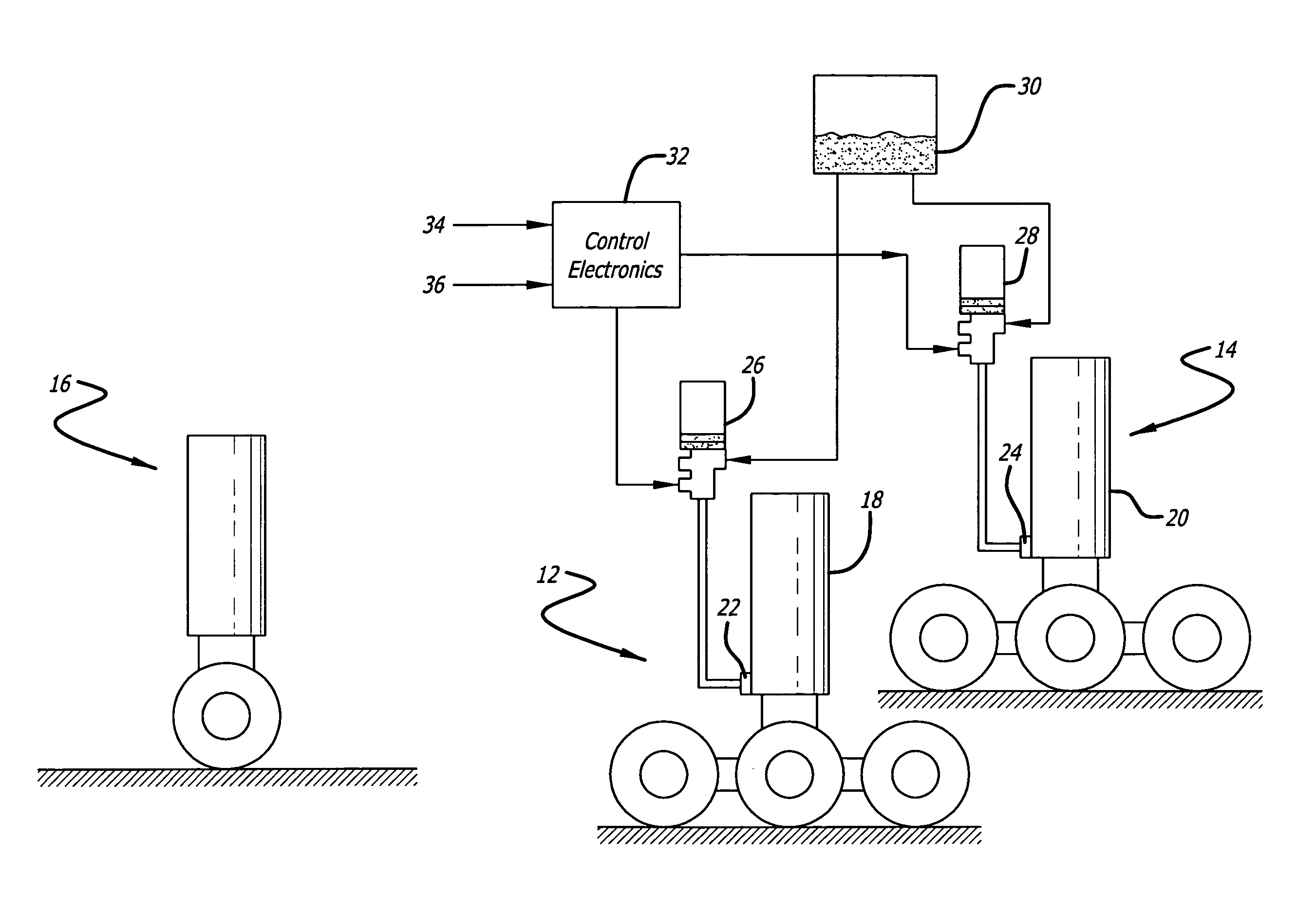
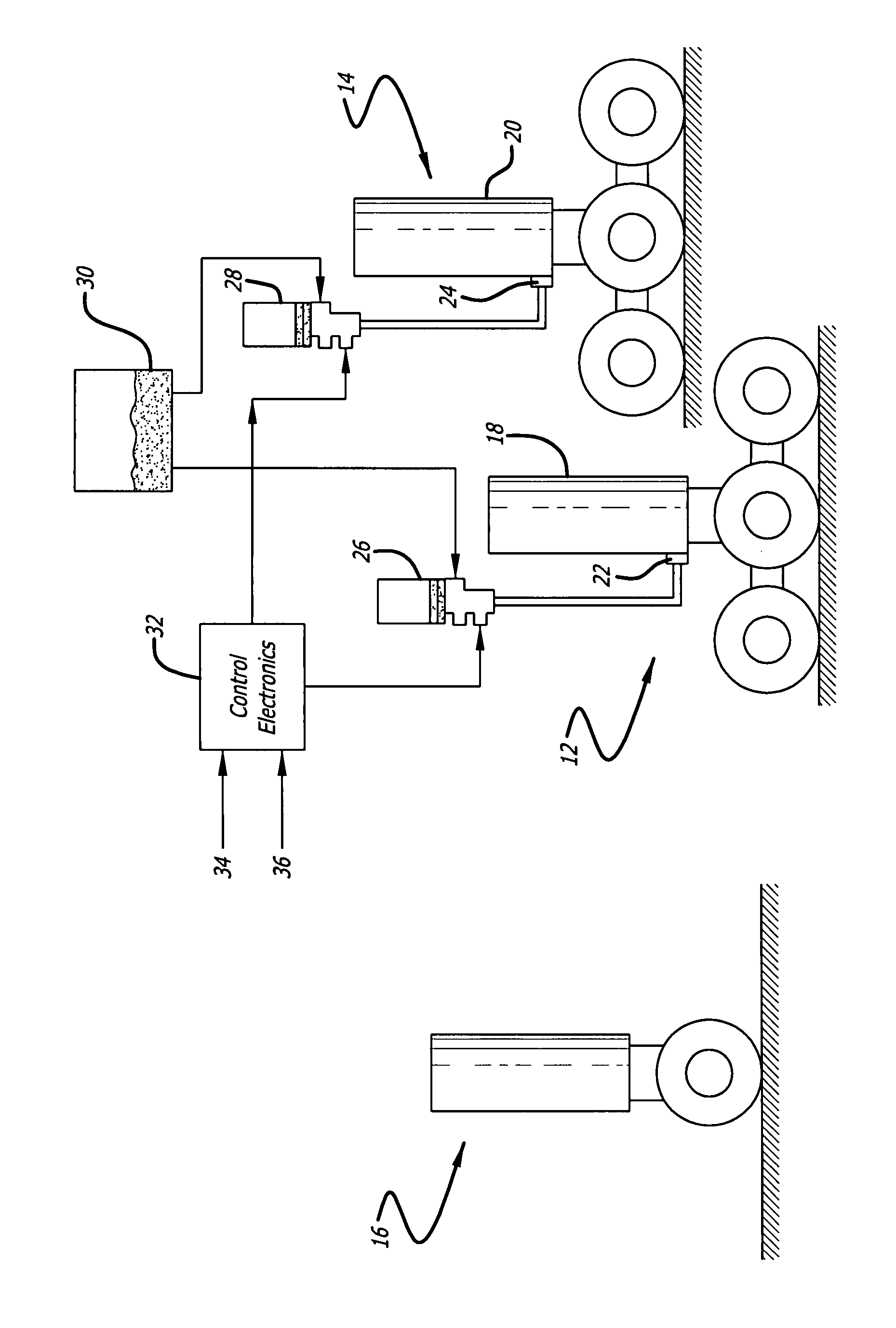
[0012]FIGURE 1 illustrates a preferred embodiment of the present invention. The illustrated device provides for the adjustment of the ride height of an aircraft. More particularly, the device allows the landing gear to be lengthened or shortened when desired and does so without affecting the spring rate. Additionally, the device may be retrofitted to existing aircraft with minimal effort and cost.

[0013]In the embodiment illustrated in the FIGURE, the device of the present invention is shown fitted to an aircraft's two main landing gear 12, 14, while the nose gear 16 remains unmodified. Each landing gear includes a strut 18, 20 that includes a piston slidably received within a cylinder. The strut contains both oil as well as a gas and is configured in the conventional manner wherein compression of the piston into the cylinder simultaneously causes the gas to be compressed and the oil to flow through restrictive flowpaths. The gas thereby serves as a spring to support the load exerted...


PUM


Abstract

A mechanism for increasing the ride height of aircraft by selectively increasing the hydraulic fluid content within landing gear struts. By increasing the hydraulic fluid volume within a strut, the strut is lengthened without adversely affecting its spring rate while the ability to withdraw fluid from a strut maintains the ability of the strut to absorb the impact of landing. The mechanism is readily retrofitable to existing landing gear systems to accommodate more efficient under the wing intake designs and to reduce the likelihood of FOD during taxiing at minimal cost and with very a minimal increase in the aircraft weight.

Description

CROSS-REFERENCES TO RELATED APPLICATIONS[0001]This application is based upon and claims priority from U.S. Provisional Application No. 60 / 783,259, filed Mar. 17, 2006.BACKGROUND OF THE INVENTION[0002]The present invention generally relates to aircraft landing gear and more particularly pertains to landing gear with adjustable ride height.[0003]In the design of an aircraft having engines mounted under the wing, the landing gear must be sufficiently long in order to provide adequate engine ground clearance. Additional length allows the engine inlets to be designed for more economical operation in flight (i.e. less drag) and the engines themselves would be less prone to damage during on-ground operations due to the ingestion of FOD (Foreign Object Damage). However, a longer landing gear adds considerable weight and some expense to the aircraft. This is particularly true when modifying an existing aircraft design to stretch the fuselage or add larger diameter engines, etc., because revi...

Claims


Application Information

Patent Timeline
Patent Type & Authority Patents(United States)
IPC IPC(8): B64C25/00B64C25/58
CPCB64C25/001B64C2025/008
Inventor DEVLIEG, GARRETT H.
Owner HYDRO AIRE AEROSPACE CORP
Why Eureka
Try Eureka