Vibration damper with adjustable damping force

a damping force and vibration damper technology, which is applied in the direction of liquid based dampers, springs/dampers, shock absorbers, etc., can solve the problem of difficulty in determining the closing behavior of the velocity-dependent damping valve, and achieve the effect of simplifying the production of the cylinder and minimizing the consequences of any leakag

Inactive Publication Date: 2012-11-13
ZF FRIEDRICHSHAFEN AG
View PDF26 Cites 68 Cited by
  • Summary
  • Abstract
  • Description
  • Claims
  • Application Information

AI Technical Summary

Benefits of technology

[0005]A great advantage is that, as a result of the upstream position of the velocity-dependent third damping valve, the damping force characteristic of the vibration damper can be determined independently of the first adjustable damping valve. The volume which is displaced by the velocity-dependent third damping valve corresponds to the volume of the inward-traveling piston rod. The damping force which is present then depends only on the velocity of the piston rod and on the damping force characteristic of the velocity-dependent third damping valve. How the displaced volume is divided after it leaves the velocity-dependent third damping valve is irrelevant. As a result, the second damping valve, that is, for example, a bottom valve, and the first adjustable damping valve can be designed more effectively to provide the desired damping force characteristic.
[0007]The distributor element can be designed as an extension of the cylinder. In principle, the distributor element could also be installed in a section of a hose outside the vibration damper. Making it part of the cylinder, however, minimizes the consequences of any leakage which may occur. This multi-part solution simplifies the production of the cylinder, in that a simple tube can be used for the working spaces on the two sides of the piston, whereas the extension, which contains the separating disk as an integral part can be made advantageously as a casting or forging.

Problems solved by technology

It is therefore very difficult to determine the closing behavior of the velocity-dependent damping valve.

Method used


Image

  • Vibration damper with adjustable damping force
  • Vibration damper with adjustable damping force
  • Vibration damper with adjustable damping force

Examples


Embodiment Construction

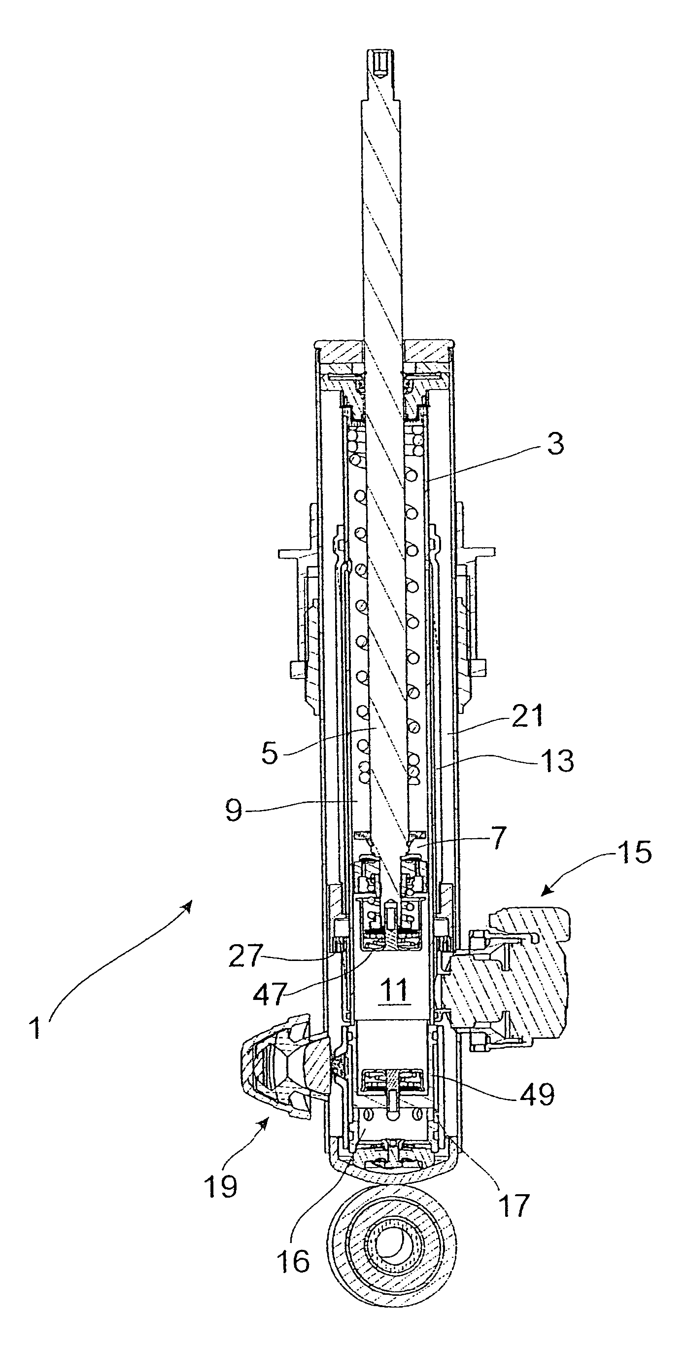
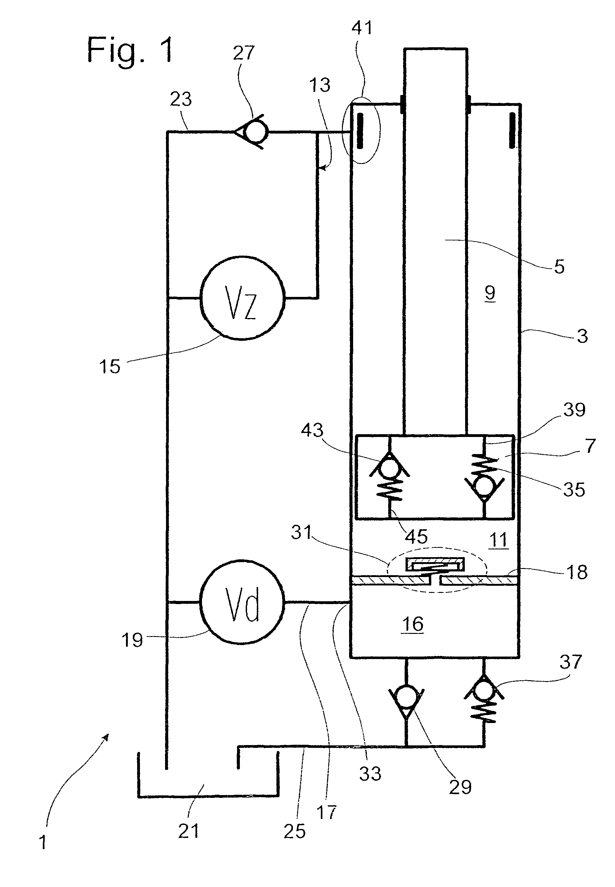
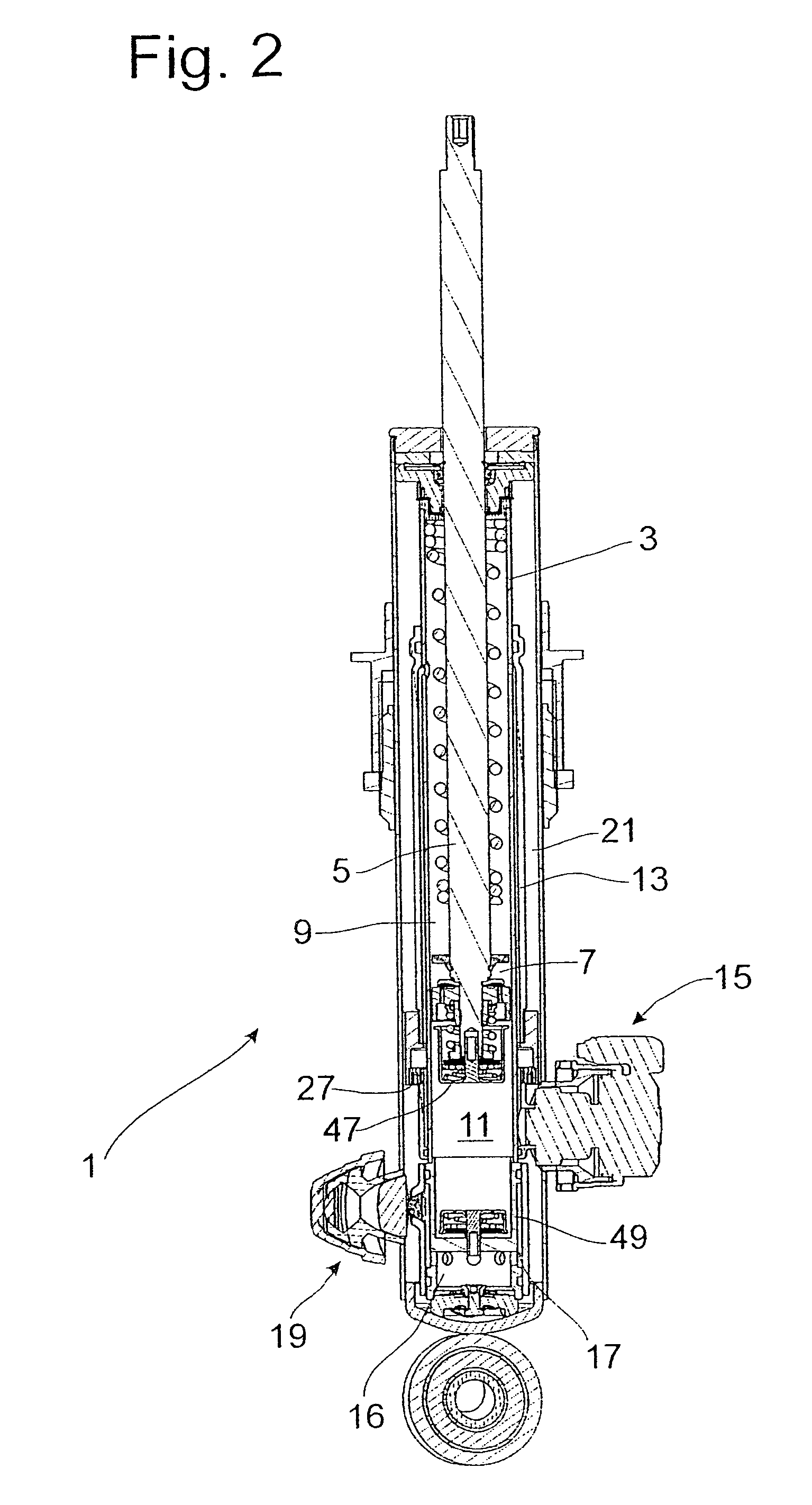
[0015]FIG. 1 is a schematic block diagram of a vibration damper 1, which comprises a cylinder 3 filled with a damping medium, in which cylinder a piston rod 5 carrying a piston 7 is guided with freedom of axial movement. The piston 7 divides the cylinder 3 into a working space 9 on the side of the piston rod 5 and a working space 11 on the side away from the piston rod 5. In principle, the piston 7 can be a simple displacement element without through-channels. The working space 9 on the piston rod side is connected by a fluid connection 13 to an adjustable damping valve 15. Adjacent to the working space 11 on the side away from the piston rod is a distribution space 16, which has a fluid connection 17 leading to a separately adjustable damping valve 19. Between the distribution space 16 and the working space 11 on the side away from the piston rod there is a separating disk 18. The damping medium displaced into the adjustable damping valves 15, 19 from the working spaces 9, 11 flows...


PUM


Abstract

The vibration damper with an adjustable damping force includes a cylinder filled with a damping medium, a piston rod axially movable in the cylinder and carrying a piston which divides the cylinder into a first working space on the piston rod side and a second working space on the side away from the piston rod, a first adjustable damping valve which is connected to at least one of the two working spaces by means of a fluid connection, at least one second valve which is connected hydraulically in parallel to the first adjustable damping valve, and a third damping valve arranged in series to and upstream from both the first and second valves, the third damping valve moving in a closing direction as a function of a flow velocity of the damping medium through the third damping valve.

Description

BACKGROUND OF THE INVENTION[0001]The invention relates to a vibration damper with adjustable damping force.[0002]DE 10 2004 054 474 B3 describes a vibration damper with adjustable damping force, comprising a piston rod, which is installed together with a piston with freedom of axial movement in a cylinder filled with damping medium, wherein the piston divides the cylinder into a working space on the side of the piston rod and a working space on the side away from the piston rod. The vibration damper further comprises an adjustable damping valve, which is connected to at least one of the two working spaces by a fluid connection. Another damping valve which moves in the closing direction as a function of the flow velocity of the damping medium is connected in series, relative to the flow of the damping medium, to the adjustable damping valve. A pressure-limiting valve in the form of a bottom valve is connected hydraulically in parallel to the adjustable damping valve. In this design, ...

Claims


Application Information

Patent Timeline
Patent Type & Authority Patents(United States)
IPC IPC(8): F16F9/10
CPCF16F9/512F16F9/516F16F9/32F16F9/34F16F9/50
Inventor FOSTER, ANDREASWIRTH, ALFREDGILSDORF, HEINZ-JOACHIMKUTSCHE, THOMAS
Owner ZF FRIEDRICHSHAFEN AG
Why Eureka
Try Eureka